
Calibration sub-system for telecommunication systems

Active Publication Date: 2014-12-09
COMMSCOPE TECH LLC
View PDF13 Cites 1 Cited by
  • Summary
  • Abstract
  • Description
  • Claims
  • Application Information

AI Technical Summary

Benefits of technology

The patent text describes a method for calibrating a DAS unit by selecting an I or Q component that affects the output power of an unwanted signal component and selecting modification schemes for it. The test signals generated based on the modifications are used to determine the output power. The optimal modification scheme is determined to minimize the output power of the unwanted signal component. This method helps to improve the performance of the DAS unit and reduce interference.

Problems solved by technology

One disadvantage of using direct conversion transmitters is the generation of undesirable signal components such as local oscillator leakage signals.
However, errors in local oscillator circuits may cause the transmitter to emit power at or near the carrier frequency.
The undesired signal component transmitted at the carrier frequency is a local oscillator leakage signal that can reduce the performance of the transmitter.
Another disadvantage of using direct conversion transmitters is the generation of undesirable sideband image signals.
Sideband image signals can be caused by gain imbalance and errors in a quadrature-mixing phase difference between an in-phase (“I”) component and a quadrature (“Q”) component of a complex uplink signal.
A gain imbalance can be caused by an uplink signal having an I component and a Q component with different signal powers.
A quadrature-mixing phase difference error can be caused by oscillators of an I / Q modulator or demodulator using signals that do not differ by exactly ninety degrees.
Both gain imbalance and quadrature-mixing phase errors can generate sideband images of sideband signal components.
I / Q gain imbalance and I / Q phase difference errors in quadrature mixing can cause the power of sideband image signal components to exceed a spectral mask for a telecommunication system.

Method used


Image

  • Calibration sub-system for telecommunication systems
  • Calibration sub-system for telecommunication systems
  • Calibration sub-system for telecommunication systems

Examples


example implementation

in MATLAB

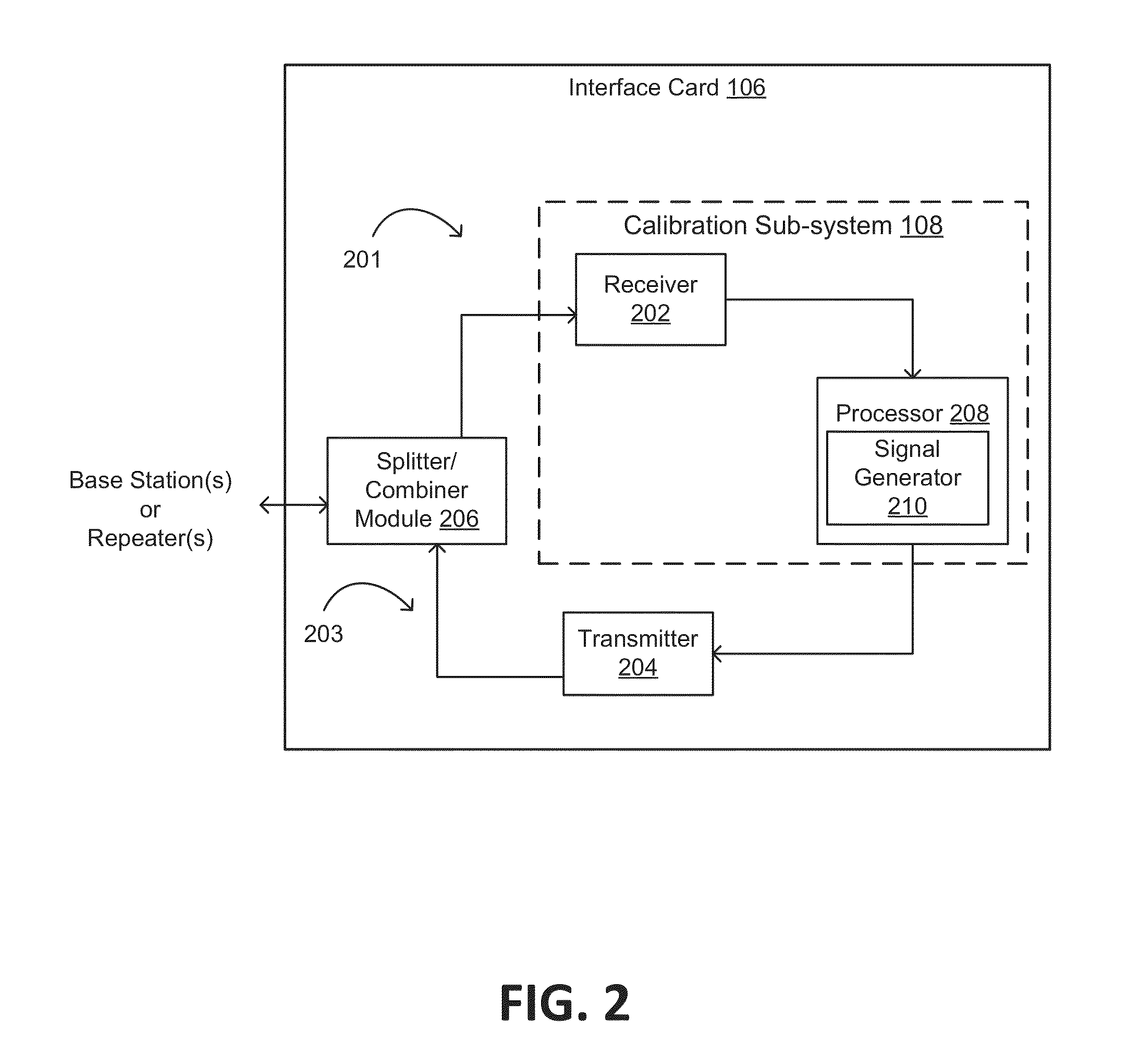
[0157]Appendix 1 provides an example of a Matlab program demonstrating generation of a test input signal. The test signal can include a single tone of 20 MHz. This test signal can be a stimulus signal for a transmitter to generate local oscillator leakage signal components and / or sideband image signal components such that a receiver tuned to or otherwise configured to receive a frequency used by the transmitter can detect the output power of local oscillator leakage signal components and / or sideband image signal components. An optimization algorithm can be applied to cancel the local oscillator leakage signal components and / or sideband image signal components. The amplitude of 1600 can be used to generate a local oscillator leakage signal component and / or the sideband image signal component having sufficient power to be detected by a receiver and to avoid clipping by the transmitter.

[0158]Appendix 1 also provides an example of a Matlab program demonstrating operation of a c...


PUM


Abstract

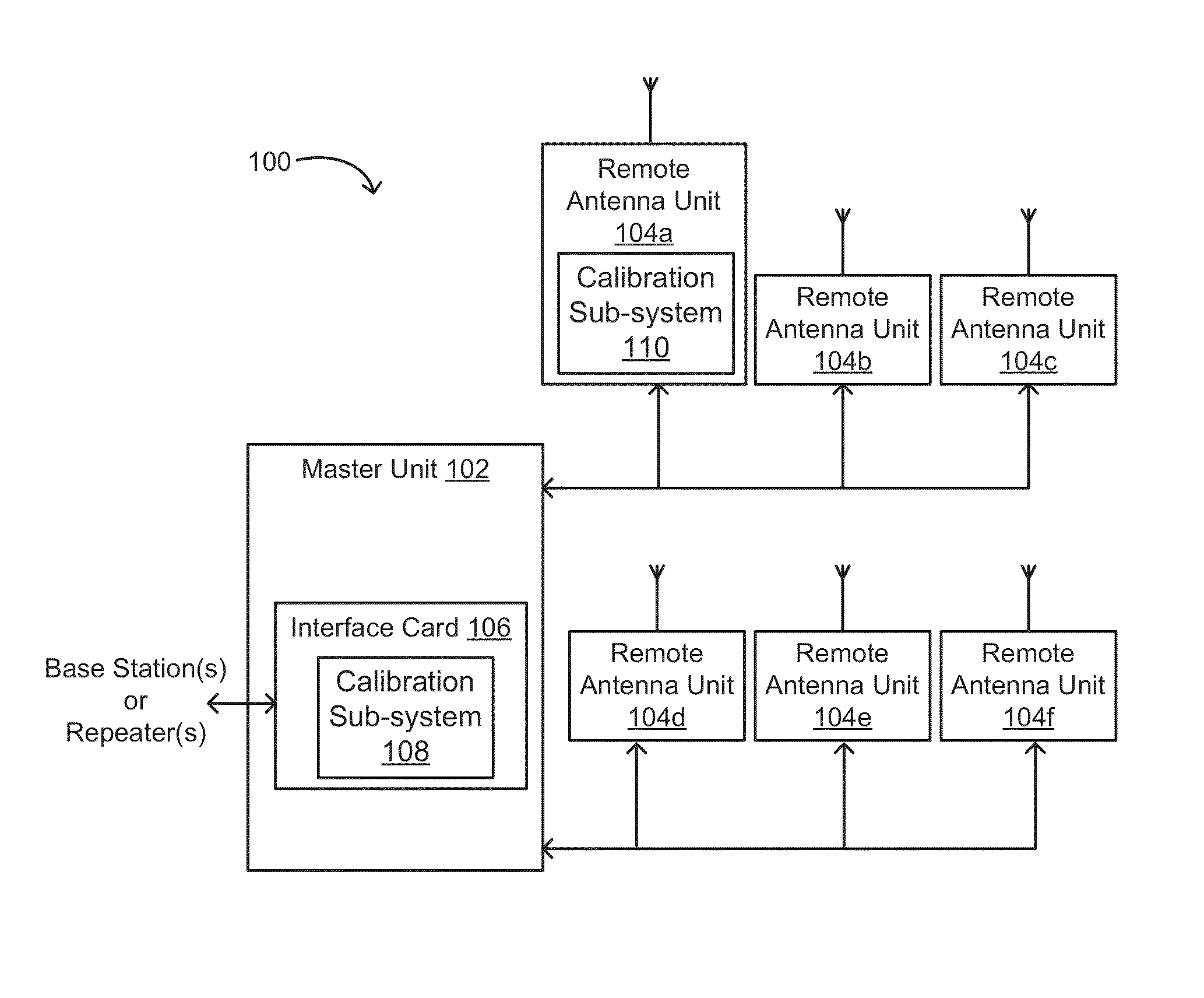
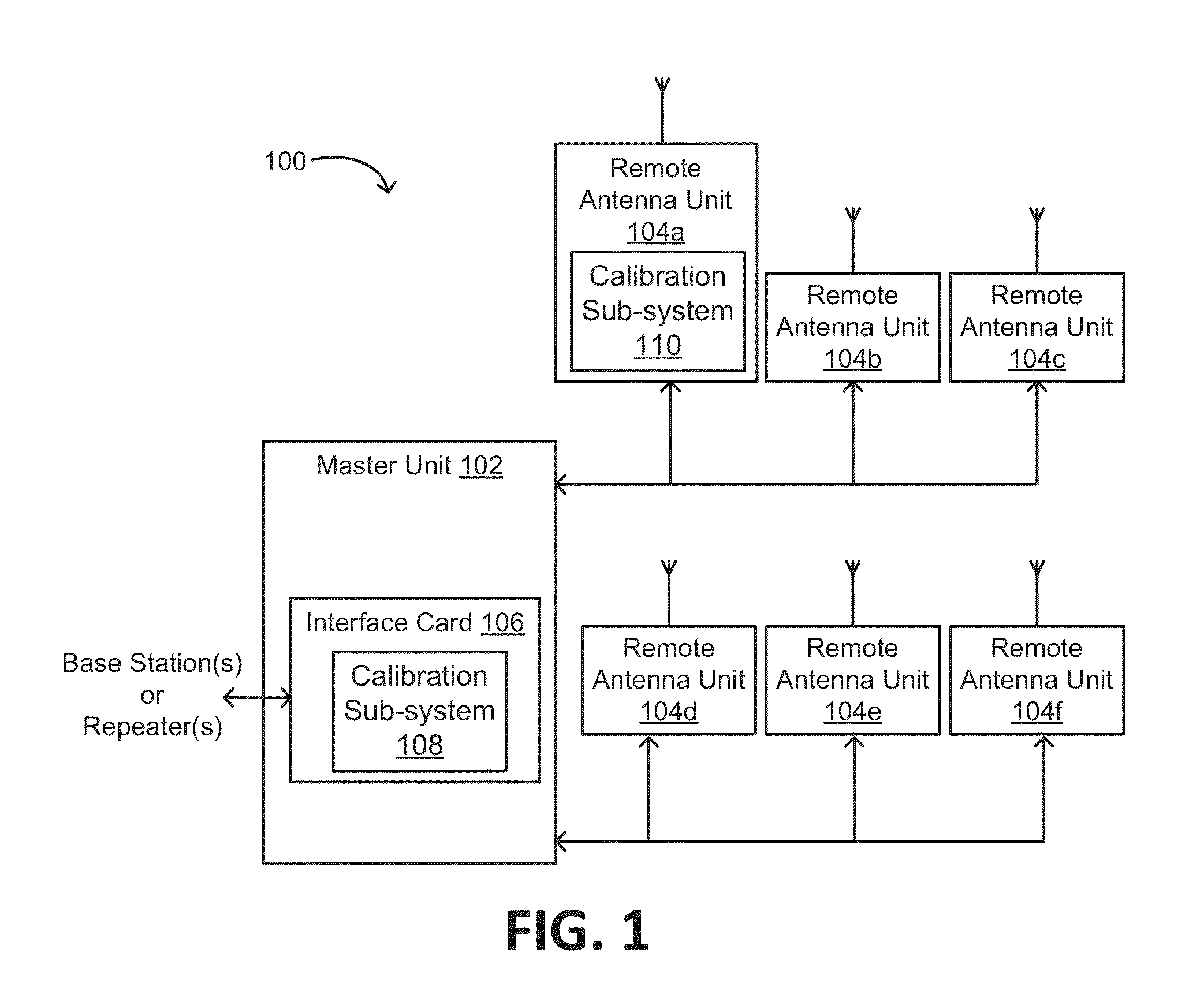
A calibration sub-system for calibrating a unit of a distributed antenna system is provided. The calibration sub-system includes a signal generator, a receiver, and a processor. The signal generator provides test signals to a communication path that are generated based on modification schemes for an in-phase signal component (“I component”) or a quadrature signal component (“Q component”). The receiver receives output signals generated from test signals. The processor determines output power values for an undesirable signal component of the output signals. Each output power value is a Taylor series function or a polynomial function of a respective modification scheme for the I or Q component of the respective test signal. The processor determines an optimal modification scheme for the I or Q component that minimizes an output power of the undesirable signal component. An output value of the function is minimized by having the optimal modification scheme as an input.

Description

CROSS-REFERENCE TO RELATED APPLICATION[0001]This application claims priority to U.S. Provisional Application Ser. No. 61 / 648,241 filed May 17, 2012 and titled “Calibration Sub-System for Telecommunication systems,” the contents of which are hereby incorporated by reference.COPYRIGHT NOTIFICATION[0002]A portion of the disclosure of this patent document contains material that is subject to copyright protection. The copyright owner has no objection to the facsimile reproduction by anyone of the patent document or the patent disclosure, as it appears in the Patent and Trademark Office patent file or records, but otherwise reserves all copyright rights whatsoever.TECHNICAL FIELD[0003]This disclosure relates generally to telecommunication systems and more particularly relates to reducing local oscillator leakage power and sideband image power in telecommunication systems.BACKGROUND[0004]Units of a telecommunication system, such as a master unit in a distributed antenna system (“DAS”), may...

Claims


Application Information

Patent Timeline
IPC IPC(8): H04B17/00H04W24/02H04B3/46H04B7/02
CPCH04W24/02H04B7/022H04B17/0062H04B17/21
Inventor LI, ZHAOHOBBS, NEIL TOWNSEND
Owner COMMSCOPE TECH LLC
Learn More