Multi-phase rotary machine control apparatus and electric power steering system using the same
a control apparatus and multi-phase technology, applied in the direction of electric generator control, dynamo-electric converter control, dynamo-electric gear control, etc., can solve the problems of short circuit, increased power output of normal power supply sources for compensation, and same problems, so as to minimize the reduction of the output power of an inverter
- Summary
- Abstract
- Description
- Claims
- Application Information
AI Technical Summary
Benefits of technology
Problems solved by technology
Method used
Image
Examples
first embodiment
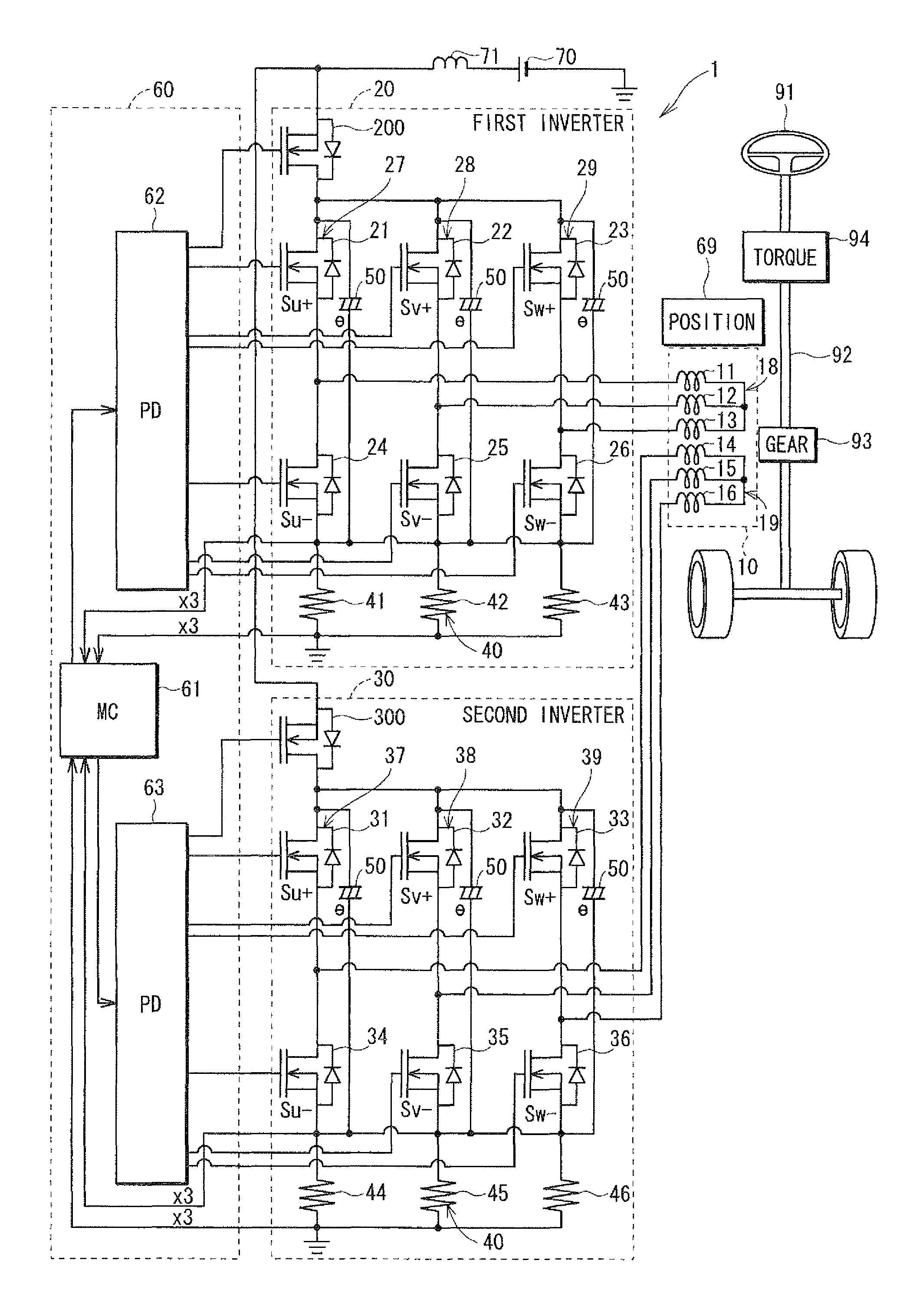
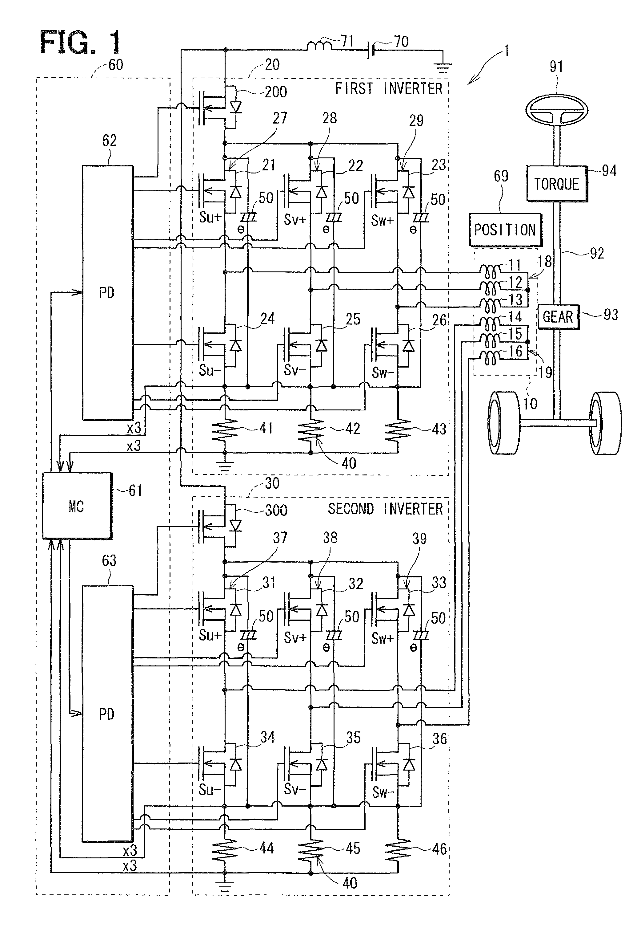
[0022]Referring first to FIG. 1, a multi-phase motor control apparatus 1 is provided for controlling the operation of a multi-phase electric motor 10, which is a rotary machine. The motor 10 is used in an electric power steering system (EPS) for power-assisting the steering operation of a vehicle. The motor 10 drives a column shaft 92, which is a rotation shaft of a steering wheel 91 of the vehicle, through a gear 93 to generate a rotation torque so that the steering operation of the steering wheel 91 is assisted. More specifically, when the steering wheel 91 is operated by a driver of the vehicle, a steering torque generated by the column shaft 92 is detected by a torque sensor 94. A vehicle speed is detected by a speed sensor (not shown) and acquired through a controller-area-network (CAN, not shown). The motor 10 is controlled in accordance with the detected torque and the detected vehicle speed.
[0023]The motor 10 is a three-phase brushless motor, which drives the gear 93 in the ...
second embodiment
[0066]According to the second embodiment, the multi-phase motor control apparatus 1 is configured similarly as in the first embodiment. However, the control part 60 is configured to perform the failure-time control as shown in FIG. 6.
[0067]In FIG. 6, the failure-time control is shown with respect to the off-failure of the U1 low-side FET 24 in the first inverter 20 as an example. The three-phase currents Iu1, Iv1, Iw1 supplied to the first coil set 18 and the generated torque Tq1 are the same as FIG. 4B. In the first embodiment, as shown in FIG. 5, the total torque Tq3 decreases at two electric angles in correspondence to the decrease of torque Tq1 in the first coil set 18. In the second embodiment, therefore, the second inverter part 30 is also controlled to compensate for the torque decrease in the first coil set 18.
[0068]According to the second embodiment, a torque difference between two torques is calculated. One torque is generated when the first inverter part 20 is controlled ...
PUM
 Abstract
Description
Claims
Application Information
 - R&D
- Intellectual Property
- Life Sciences
- Materials
- Tech Scout
- Unparalleled Data Quality
- Higher Quality Content
- 60% Fewer Hallucinations
Browse by: Latest US Patents, China's latest patents, Technical Efficacy Thesaurus, Application Domain, Technology Topic, Popular Technical Reports.
© 2025 PatSnap. All rights reserved.Legal|Privacy policy|Modern Slavery Act Transparency Statement|Sitemap|About US| Contact US: help@patsnap.com


