Image display apparatus, method, program, and recording medium

a technology of image display and return operation, applied in the field of image display, can solve the problems of not being able to move to an image portion, affecting the viewing experience of even an a4-size document, and increasing the burden of users, so as to reduce the burden of users in performing return operations on the screen display

Active Publication Date: 2011-03-31
FUJIFILM CORP
View PDF11 Cites 5 Cited by
  • Summary
  • Abstract
  • Description
  • Claims
  • Application Information

AI Technical Summary

Benefits of technology

[0016]According to the present invention, when a user moves a display location to partially display text that is described in an image over a wide area, the burden of the user in performing return operations with respect to the screen display can be reduced

Problems solved by technology

However, since the resolution and screen area of a portable terminal is extremely small compared to a personal computer, it is troublesome to view even an A4 size document.
When reading a long sentence, the number of these movements from the end of one line to the start of another line increases, and feeling of an ope

Method used


Image

  • Image display apparatus, method, program, and recording medium
  • Image display apparatus, method, program, and recording medium
  • Image display apparatus, method, program, and recording medium

Examples


first embodiment

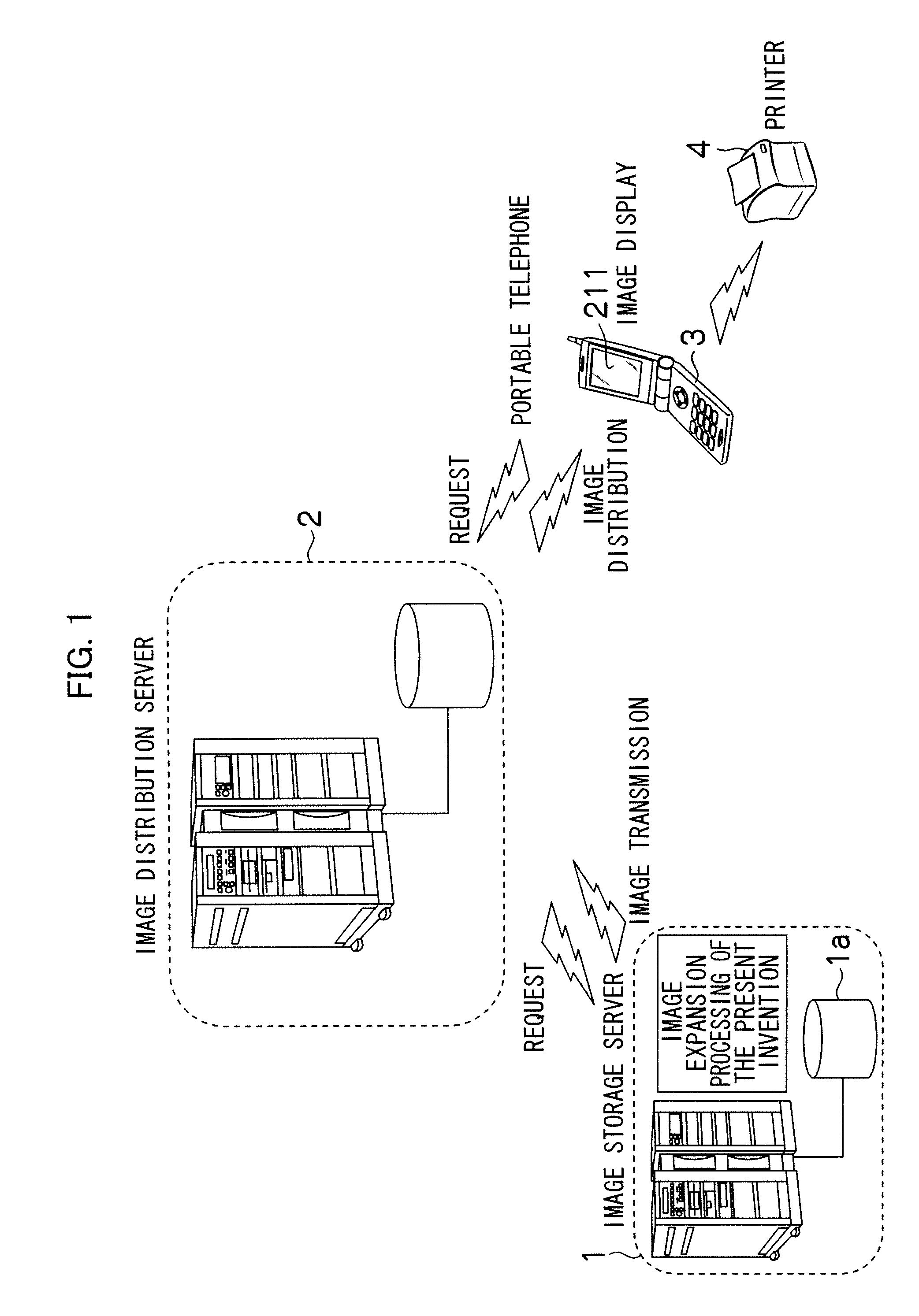
[0022]FIG. 1 illustrates a schematic configuration of an image providing system according to a preferred first embodiment of the present invention. This system includes an image storage server 1, an image distribution server 2, a portable telephone 3, and a printer 4. The image storage server 1 and the image distribution server 2 are connected by various kinds of networks such as a LAN or the Internet. The image distribution server 2 and the portable telephone 3 are connected by various kinds of networks such as a mobile phone communication network. The portable telephone 3 and the printer 4 are connected by various kinds of networks such as infrared communication.

[0023]The image storage server 1 and the image distribution server 2 are constituted by a computer, and include a CPU, a memory (RAM, ROM), a HDD, a communication unit, a data input / output circuit, a display circuit, and an operation apparatus.

[0024]When the image distribution server 2 receives a request to distribute an i...

second embodiment

[0058]The processing of S6 and thereafter in the flowchart of image display return processing of the first embodiment may be omitted. FIG. 5 illustrates a flowchart of the processing in such case. Steps S11 to S15 are the same as steps S1 to S5, respectively. However, in S15, the processing returns to S11 are performing the same processing as in S5.

third embodiment

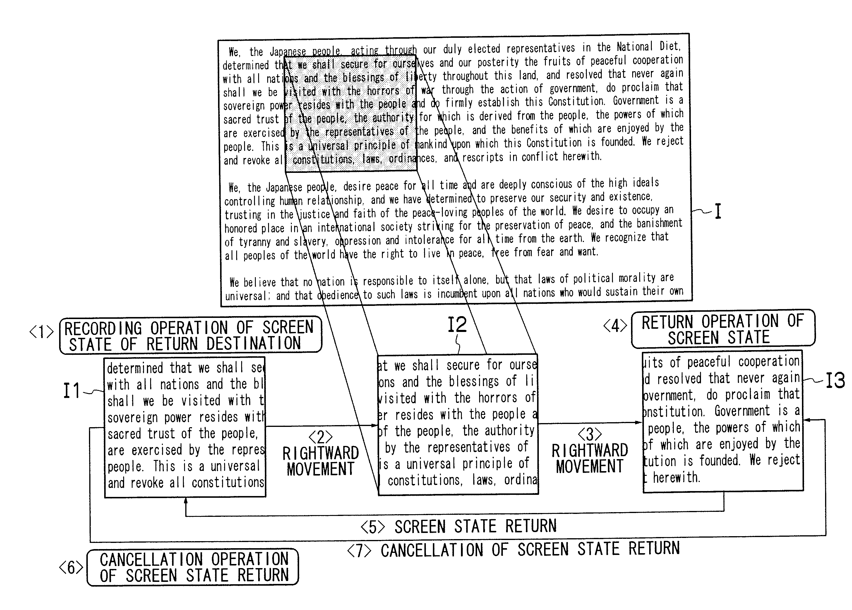
[0059]A configuration may be adopted so that in S5 or S15 the CPU 230 does not display a partial region at a position that completely matches the position coordinates included in the information of the return destination, but rather displays a nearby partial region that is in a position obtained by adding a predetermined correction value that is previously stored in the rewritable ROM 234 to the position coordinates included in the information of the return destination. For example, in the case of the text written from left to right as shown in FIG. 4, it is considered that at the time when the partial region 13 is being displayed the user is reading through one line of the document. Accordingly, assuming that the position coordinates of the return destination section included in the information of the return destination of the RAM 231 are (X, Y), in S5 or S15 the CPU 230 may display a nearby partial region that exists at coordinates (X, Y+ΔY) that are obtained by adding a display s...


PUM


Abstract

According to the image display method, apparatus, and program of the present invention, when a user moves a display location to partially display text that is described in an image over a wide area, the burden of the user in performing return operations with respect to the screen display can be reduced by freely selecting and storing a return destination of the screen from among displayed partial regions in accordance with a user instruction, and thereafter returning to the display of the stored partial region in accordance with an instruction of the user.

Description

BACKGROUND OF THE INVENTION[0001]1. Field of the Invention[0002]The present invention relates to movement and return of a displayed portion of an image.[0003]2. Description of the Related Art[0004]Japanese Patent Application Laid-Open No. 2007-256529 points out the complexity of movement operations when viewing text of a length that can not entirely fit on a small screen such as a screen of a portable terminal, and also points out that movement from the end of a paragraph to the start of a paragraph is troublesome when viewing text that includes a plurality of paragraphs. According to the method described in Japanese Patent Application Laid-Open No. 2007-256529, text is analyzed in advance to determine the order for viewing paragraphs or lines, and movement of the screen is controlled in accordance with the determined order.[0005]According to WO 2005 / 106628, in a state in which an operation screen for operating one frame in a frame page is being displayed, it is determined whether a...

Claims


Application Information

Patent Timeline
IPC IPC(8): G09G5/00G06F3/048G06F3/0485
CPCG09G5/346G09G2370/022G06T3/40G06T11/60G06T3/00G06T5/001G06T2200/24
Inventor OTANI, HIROSHI
Owner FUJIFILM CORP
Why Eureka
Try Eureka