Driving method of liquid discharge head and liquid discharge apparatus

a liquid discharge head and driving method technology, applied in the direction of printing, inking apparatus, other printing apparatus, etc., can solve the problems of unachievable increase in efficiency of individual liquid discharge chambers, unfavorable rapid return of meniscus to initial position in discharge port, and unclear points on whether the refilling ability is enhanced

Inactive Publication Date: 2011-03-31
CANON KK
View PDF3 Cites 9 Cited by
  • Summary
  • Abstract
  • Description
  • Claims
  • Application Information

AI Technical Summary

Benefits of technology

[0017]In order to solve the above problems, an object of the invention is to quickly return a menis

Problems solved by technology

However, when the description of Japanese Patent Application Laid-Open No. 2008-155537 is examined thoroughly, there are many unclear points on whether the refilling ability is enhanced.
Accordingly, it is thought that the increase in efficiency of the refilling ability of the individual liquid chambers cannot be expected.
In addition, in the technique disclosed in Japanese Patent Application Laid-Open No. 2008-155537, it is unclear whether the meniscus can be promptly returne

Method used


Image

  • Driving method of liquid discharge head and liquid discharge apparatus
  • Driving method of liquid discharge head and liquid discharge apparatus
  • Driving method of liquid discharge head and liquid discharge apparatus

Examples


example 1

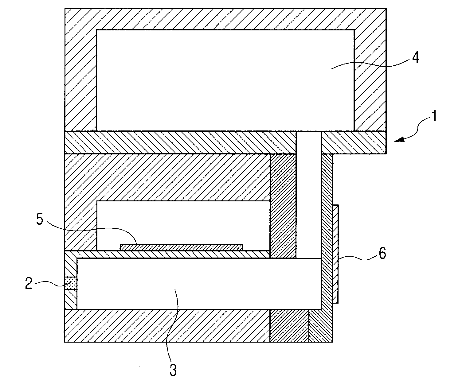
[0041]Examples of the invention will be described in detail. In this example, the liquid discharge head 1 illustrated in FIGS. 2A and 2B was manufactured. The discharge port 2 is a circular hole with a diameter of 10 μm and an orifice plate thickness of 15 μm. Liquid to be discharged is clear ink (with 66% PEG600, 33% pure water, and 1% surfactant) and has a viscosity of 40×10−3 [Ps·s] and a surface tension of 38×10−3 [N / m] (both are values at room temperature).

[0042]This example is for the purpose of discharging high-viscosity ink. Therefore, in order to reduce loss of discharge energy as much as possible, the push-shot method is employed. FIG. 3A is a diagram illustrating a voltage waveform applied to the first actuator 5, and FIG. 3B is a diagram illustrating a voltage waveform applied to the second actuator 6. In addition, FIG. 3C is a graph showing a height of a meniscus of the liquid, which has been drawn into the discharge port 2 once after ink droplets are discharged from th...

example 2

[0059]Next, another example of the invention will be described. The liquid discharge head 1 used in this example is the same as that used in Example 1. The same clear ink to be discharged is used. Therefore, in the following description, description of common factors to Example 1 will be omitted.

[0060]In this example, the T4 period in FIG. 3B was started at the same time as the termination of the T3 period in FIG. 3A.

[0061]As the flow path 3 is contracted by the second actuator 6 (FIG. 2B) in the T4 period in FIG. 3B, as illustrated in FIG. 5D, the meniscus M (liquid column) is allowed to significantly project outward (toward the outside) (FIG. 3C). In this example, since ink with high viscosity is used, even in this operation, the liquid column was not cut, liquid droplets were not cut nor scattered from the liquid column.

[0062]Last, the voltage applied to the second actuator 6 (FIG. 2B) is returned to its initial state. Accordingly, the flow path 3 expands in the T5 period in FIG....

example 3

[0065]Further another example of the invention will now be described. Clear ink to be discharged in this example is the same as that used in Example 1. FIG. 7 is a diagram schematically illustrating the liquid discharge head 1 according to this example. The discharge port 2 is a circular hole with a diameter of 10 μm and an orifice plate thickness of 15 μm. In the following description, description of common factors to Example 1 will be omitted.

[0066]A part of the flow path 3 illustrated in FIG. 7 which extends in the same direction as the center axis of the discharge port 2 has a length of 6,000 μm, a width of 100 μm, and a height of 200 μm. The flow path 3 from the curved part to the connection part of the common liquid chamber 4 has a length of 1,200 μm, a width of 100 μm, and a height of 200 μm, and a portion of which is provided with a squeezed portion with a width of 15 μm. An opening area of a first opening 8 is 600 μm×100 μm, and an opening area of a second opening 9 is 100 ...


PUM


Abstract

A driving method of a liquid discharge head including discharge ports, flow paths communicated with the discharge ports, a first actuator provided on the flow paths, a second actuator provided at a position further from the discharge port than the first actuator of the flow paths, and a common liquid chamber communicated with the flow paths, includes: contracting the flow path and expanding the flow path by the first actuator to discharge liquid from the discharge port; starting contraction of the flow path the second actuator when or before flow of liquid from the common liquid chamber to the discharge port in the vicinity of the second actuator, disappears to allow a meniscus of liquid, located at an inner position of the flow path, to project from the discharge port; and starting expansion of the flow path by the second actuator while the meniscus projects from the discharge port.

Description

BACKGROUND OF THE INVENTION[0001]1. Field of the Invention[0002]The present invention relates to a driving method of a liquid discharge head using an actuator as a source for generating liquid discharge energy, and a liquid discharge apparatus including the liquid discharge head using the actuator as the source for generating liquid discharge energy. The present invention can be applied to a printing apparatus for printing text or images on paper, fabric, leather, or nonwoven fabric, and a patterning apparatus or coating apparatus for applying liquid to a substrate, plate material, solid object or the like.[0003]2. Description of the Related Art[0004]Various proposals have been made for a liquid discharge head mounted in a liquid discharge apparatus which can be represented by an ink jet recording apparatus. Particularly, a liquid discharge head using an actuator as a source for generating liquid discharge energy has a merit in that any type of liquid (ink) is suitable for discharge...

Claims


Application Information

Patent Timeline
IPC IPC(8): B41J29/38
CPCB41J2/04533B41J2/04581B41J2/04588B41J2/045B41J29/38B41J2002/14338B41J2002/14467B41J2/175B41J2202/05
Inventor KITAKAMI, KOICHISASAGAWA, NAOTO
Owner CANON KK
Why Eureka
Try Eureka