Supercharge Your Innovation With Domain-Expert AI Agents!

Electromagnetic shielding coating and lens module utilizing the same

a technology of electromagnetic shielding coating and lens module, applied in the field of lenses, can solve the problems of weak adherence between the light shielding coating and the optical coating, and significant stress between the light shielding coating

Inactive Publication Date: 2011-03-31
HON HAI PRECISION IND CO LTD
View PDF1 Cites 4 Cited by
  • Summary
  • Abstract
  • Description
  • Claims
  • Application Information

AI Technical Summary

Benefits of technology

The present patent relates to an electromagnetic shielding coating for lens modules and aims to solve the problem of significant stress between the light shielding coating and the electromagnetic shielding coating when the thickness of the electromagnetic shielding coating exceeds 1 μm. The technical effect of the invention is to provide an electromagnetic shielding coating that can effectively shield against electromagnetic interference while also improving adhesion between the light shielding coating and the electromagnetic shielding coating.

Problems solved by technology

However, if the lens has been covered with an optical coating, and the light shielding coating is coated on the optical coating, generally significant stress exists among the light shielding coating, the copper layer of the electromagnetic shielding coating, and the optical coating.
If the thickness of the electromagnetic shielding coating exceeds 1 μm, adherence between the light shielding coating and the optical coating becomes weak, and the light shielding coating and the electromagnetic shielding coating are easily peeled off from the optical coating.

Method used


Image

  • Electromagnetic shielding coating and lens module utilizing the same
  • Electromagnetic shielding coating and lens module utilizing the same
  • Electromagnetic shielding coating and lens module utilizing the same

Examples


first embodiment

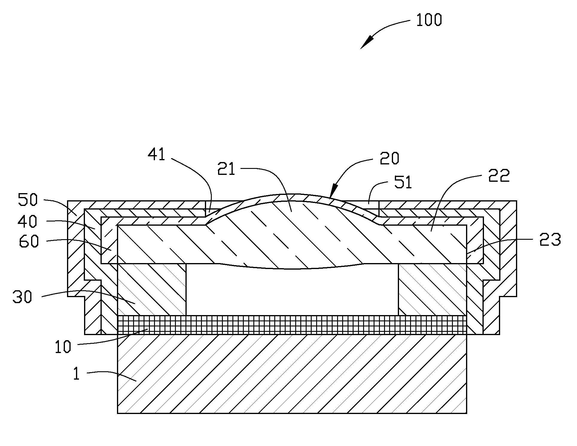
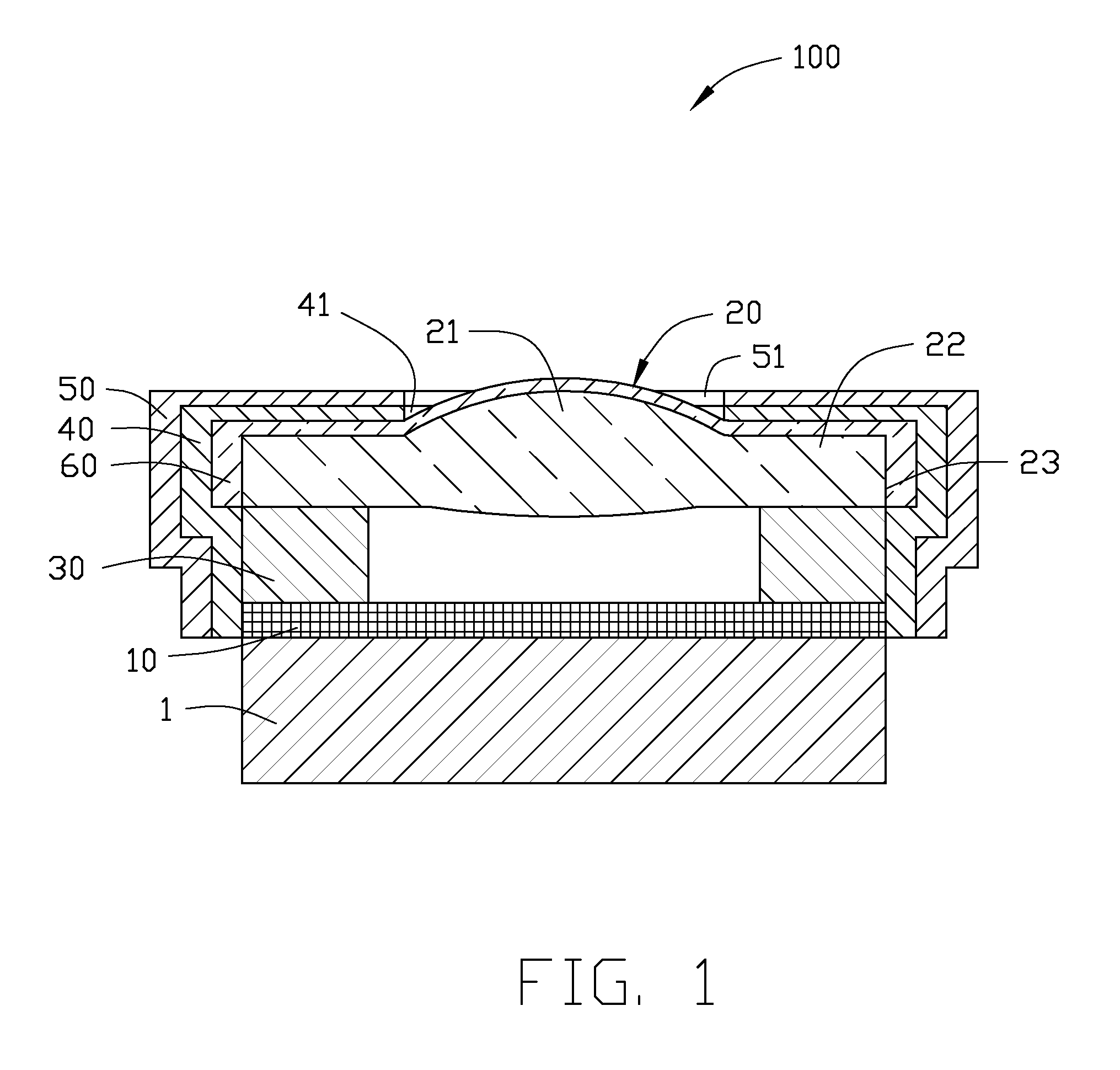
[0017]Referring to FIG. 2, the electromagnetic shielding coating 50 of a first exemplary embodiment is a mixture of stainless steel and copper. In the first embodiment, the electromagnetic shielding coating 50 is a mixture of Cr18Ni9 and copper. The electromagnetic shielding coating 50 is formed on the light shielding coating 40 by vacuum sputtering. In the mixture, increased copper proportion improves electromagnetic resistance, decreases adherence, and increases chance of electromagnetic shielding coating oxidation.

second embodiment

[0018]Referring to FIG. 3, the electromagnetic shielding coating 50 of a second exemplary embodiment includes a first metal layer 61 formed on the light shielding coating 40, a second metal layer 62 formed on the first metal layer 61, and a third metal layer 63 formed on the second metal layer 62. In the second embodiment, the first metal layer 61 only contains stainless steel. The first metal layer 61 is Cr18Ni9. The second metal layer 62 is copper. The second metal layer 62 is formed by vacuum sputtering. The third metal layer 63 is Cr18Ni9.

[0019]Referring to FIG. 4, the electromagnetic shielding coating 50 of a third exemplary embodiment includes a first metal layer 71, a second metal layer 72, and a third metal layer 73. The first metal layer 71 and the second metal layer 72 are similar to the first metal layer 61 and the second metal layer 62 of the second embodiment correspondingly. The third metal layer 63 is a mixture of Cr18Ni9 and copper. The third metal layer 73 is formed...


PUM

PropertyMeasurementUnit
thicknessaaaaaaaaaa
thicknessaaaaaaaaaa
thicknessaaaaaaaaaa

Abstract

An electromagnetic shielding coating covers a lens coated with an optical coating. A light shielding coating covers the optical coating. The electromagnetic shielding coating covers the light shielding coating. The electromagnetic shielding coating includes a first stainless steel layer and a second copper layer. The first stainless steel layer contains stainless steel, and is formed on the light shielding coating directly. The second copper layer is formed on the first metal layer.

Description

BACKGROUND[0001]1. Technical Field[0002]The present disclosure relates to lens modules and, particularly, to an electromagnetic shielding coating and lens module uitlizing the same.[0003]2. Description of Related Art[0004]Many camera modules are currently manufactured using wafer level assembly. One kind of such camera modules includes an image sensor, a lens, and a spacer. The spacer is adhered to the image sensor. The lens is stacked on the spacer. A light shielding coating covers the peripheral surface of the lens. An electromagnetic shielding coating covers the light shielding coating. The electromagnetic shielding coating includes a copper layer adhered to the light shielding coating, and a stainless steel layer adhered to the copper layer.[0005]However, if the lens has been covered with an optical coating, and the light shielding coating is coated on the optical coating, generally significant stress exists among the light shielding coating, the copper layer of the electromagne...

Claims


Application Information

Patent Timeline
Patent Type & Authority Applications(United States)
IPC IPC(8): H04N5/225H05K9/00
CPCB32B15/015H05K9/0094G02B5/208G02B1/11
Inventor HUNG, HSIN-CHIN
Owner HON HAI PRECISION IND CO LTD
Features
  • R&D
  • Intellectual Property
  • Life Sciences
  • Materials
  • Tech Scout
  • Unparalleled Data Quality
  • Higher Quality Content
  • 60% Fewer Hallucinations
Learn More