Field emission x-ray source with magnetic focal spot screening

a field emission x-ray and magnetic focal spot technology, applied in the field of x-ray sources, can solve the problems of limited data acquisition rate, complicated control of such systems, and limited speed of ct scanners

Inactive Publication Date: 2011-03-31
XINRAY SYSTEMS LLC +2
View PDF6 Cites 48 Cited by
  • Summary
  • Abstract
  • Description
  • Claims
  • Application Information

AI Technical Summary

Benefits of technology

[0012]It is an object of the present invention to provide an x-ray imaging system wherein...

Problems solved by technology

The need for mechanical rotation of the x-ray tube limits the rate of data acquisition.
Moreover, the control of such systems is complicated by the structure for mechanically rotating the x-ray tube.
Many current CT scanners acquire 2D projection images from one viewing angle at a time, and therefore the speed of the CT scanner is limited.
Such systems can be large, expensive, and have a limited range of viewing angles.
This means that all components within the rotating part of the gantry exp...

Method used


Image

  • Field emission x-ray source with magnetic focal spot screening
  • Field emission x-ray source with magnetic focal spot screening
  • Field emission x-ray source with magnetic focal spot screening

Examples


Embodiment Construction

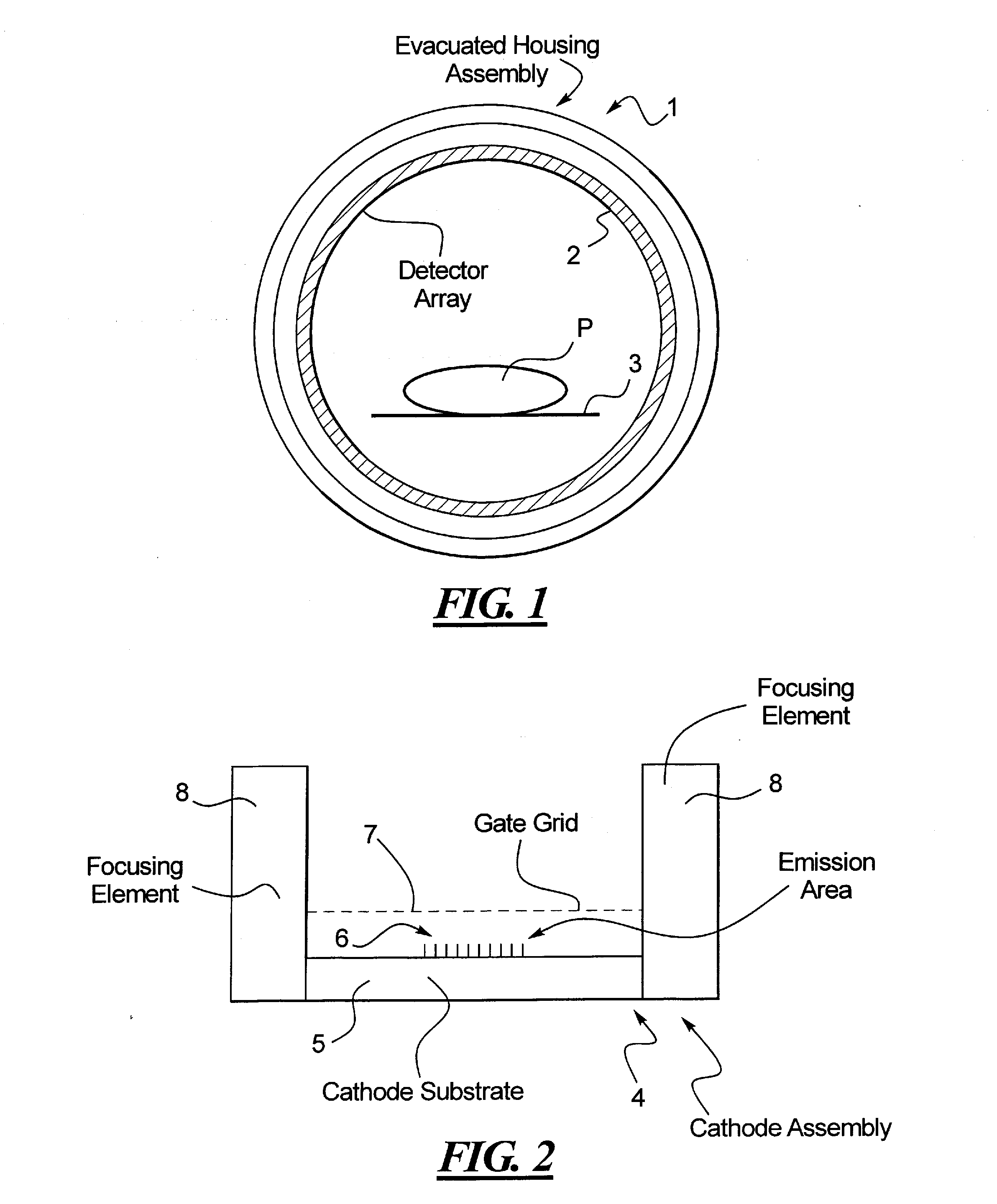
[0019]FIG. 1 schematically illustrates the use of multiple x-ray sources in accordance with the present invention in the embodiment of a computed tomography imaging apparatus. The imaging apparatus has an annular or ring-shaped evacuated housing assembly 1 which is composed of multiple x-ray sources in accordance with the present invention. The embodiment of the CT apparatus shown in FIG. 1 has a detector array ring 2 that detects the x-rays emitted from the evacuated housing assembly 1. The detector array ring 2 is offset in the longitudinal direction (i.e., the direction proceeding perpendicular to the plane of the drawing in FIG. 1) so that the x-rays emitted from the evacuated housing assembly 1 penetrate a patient P on a patient bed 3, and are then detected by individual detector elements of the detector array ring 2. The detector array ring 2, however, need not proceed continuously around the patient P, but may only occupy a portion of the total extent around the patient P, as...


PUM


Abstract

An x-ray imaging system has an x-ray source having an electron field emission source that emits an x-ray beam that strikes an elongated, stationary anode in an evacuated housing. A magnetic deflection system steers the electron beam between the electron field emission source and the anode, so that the electron beam can strike the anode at different locations, thereby causing x-rays to be emitted from those different locations, by controlling the degree of magnetic deflection. A radiation detector detects the x-rays after attenuation by an examination subject, and generates signals dependent on the detected radiation that represent an image of the subject.

Description

BACKGROUND OF THE INVENTION[0001]1. Field of the Invention[0002]The present invention concerns an x-ray source of the type suitable for x-ray imaging, and in particular a field emission x-ray source.[0003]2. Description of the Prior Art[0004]X-ray imaging is widely used in many areas of medical diagnostics and treatment, as well as for industrial inspection and testing, and for security screening. For x-ray imaging that produces a three-dimensional image of the examination subject or object, the subject is irradiated with an x-ray beam from a large number of different directions, each directional radiation resulting in a 2D projection that is detected by the radiation detector. Many known techniques exist to combine the multiple 2D projections to reconstruct a 3D image of the irradiated object therefrom.[0005]An exemplary x-ray imaging system of the above type is a computed tomography (CT) system. CT enables the reconstruction of a 3D image of the object by acquiring hundreds or tho...

Claims


Application Information

Patent Timeline
IPC IPC(8): G01N23/083H01J35/30H01J35/06
CPCH01J35/065H01J35/08H01J35/14H01J2235/086H01J2235/062H01J2235/068H01J35/30H01J35/112H01J35/153
Inventor BECKMANN, MORITZFUERST, JENSSCHARDT, PETERSPRENGER, FRANKZHOU, OTTO
Owner XINRAY SYSTEMS LLC
Why Eureka
Try Eureka