Visualization Method and Imaging System

a visualization method and imaging system technology, applied in the field of medical imaging systems, can solve the problems of frequent lack of too expensive application for clinical routines, and achieve the effect of simple spatial orientation in the vascular system

Active Publication Date: 2011-03-31
SIEMENS HEALTHCARE GMBH
View PDF14 Cites 64 Cited by
  • Summary
  • Abstract
  • Description
  • Claims
  • Application Information

AI Technical Summary

Benefits of technology

[0006]The object of the present invention is to provide a method which, with modern catheter or wire-based examination techniques, makes a simple spatial orientation in the vascular system possible; a further object of the invention is to provide a suitable device for carrying out the method.
[0015]The inventive method provides the option of visualizing a vascular system of a patient simultaneously in overview and in detail and thus for example providing a doctor with all information needed for a precise diagnosis. In such cases the inventive method can be carried out automatically or at least semi-automatically in a simple manner and with little effort.
[0016]In accordance with an embodiment of the invention a segmentation of the hollow organs is carried out on the basis of the x-ray dataset. The segmentation enables the position of the instrument to be determined more quickly and with fewer errors.
[0023]Advantageously for simple detection of the position on the individual x-ray images, the catheter has a catheter tip which is not transparent to x-rays.
[0025]In an advantageous manner the method is carried out automatically. Suitable for especially automatic execution of the method is a medical imaging system featuring an angiography x-ray system with an x-ray source and an x-ray detector, and featuring a catheter system with a catheter and a data capture unit and also featuring a control system, an imaging unit and a display unit.

Problems solved by technology

The disadvantage of these technologies is that they frequently lack orientation in the vascular system.
The disadvantage of this method is the high financial outlay for the navigation system and the additional equipping of the IVUS catheter with the position sensors, so that application for clinical routines is too costly.

Method used


Image

  • Visualization Method and Imaging System
  • Visualization Method and Imaging System
  • Visualization Method and Imaging System

Examples


Embodiment Construction

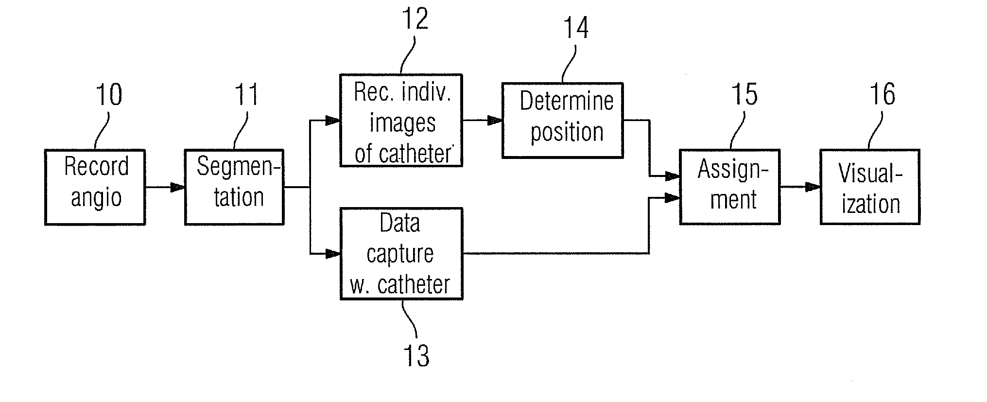
[0033]X-ray imaging and especially angiography allow spatial arrangements of vascular systems to be especially well visualized, but the corresponding vessel walls are only little visible. Other measurement methods, especially intravascular ultrasound imaging (IVUS) or optical coherence tomography (OCT), offer good visualizations of the vessel walls but have the disadvantage of overview and spatial orientation being deficient. The invention contains a method which connects x-ray imaging with a further measurement method such that a parallel display is available.

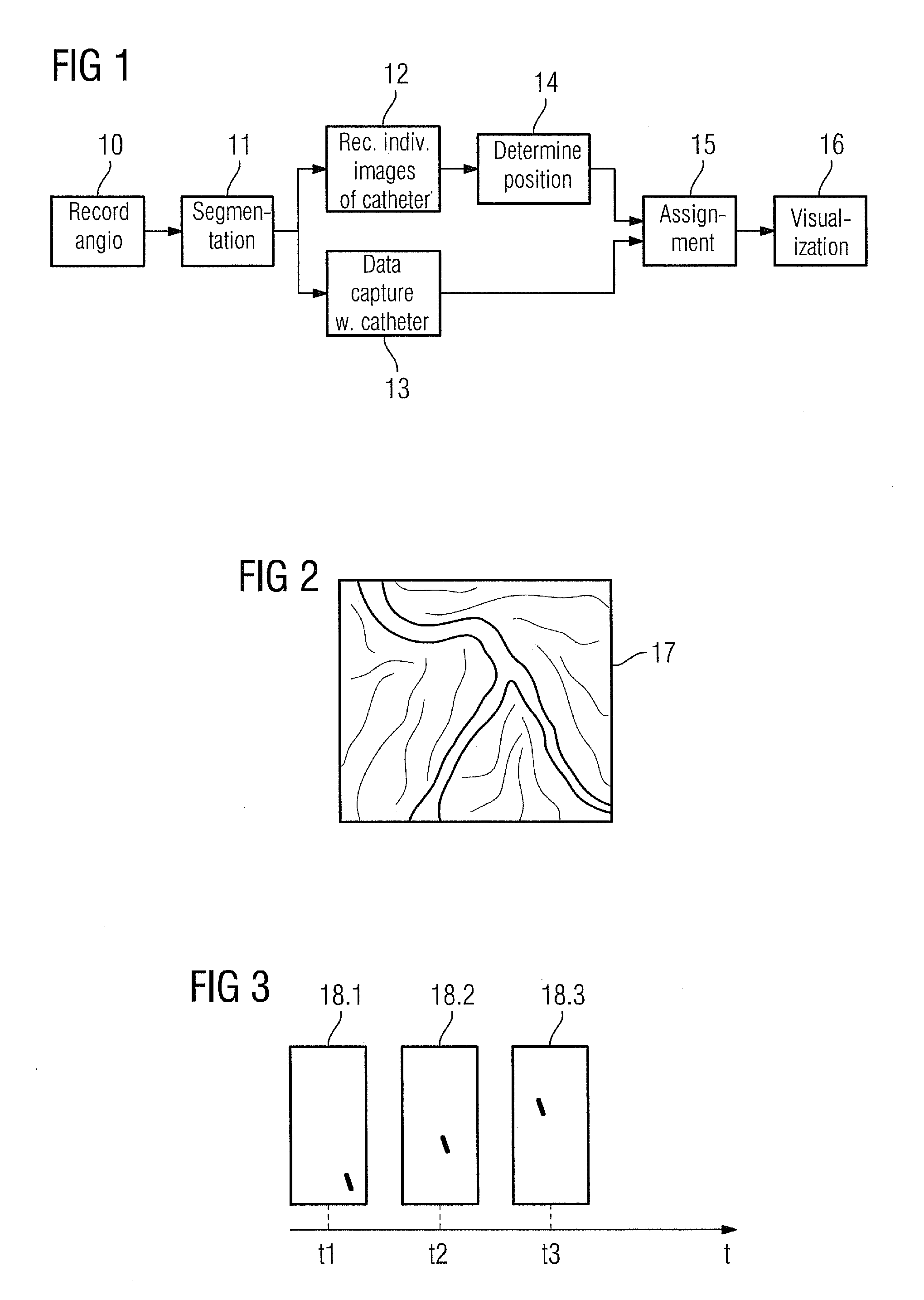
[0034]FIG. 1 shows a sequence of steps of the inventive method. In a first step 10 an x-ray image dataset, especially an angiography sequence of a hollow organ (e.g. vascular system), which is to be examined is recorded or made available from a memory. Such an angiography dataset 17 with a hollow organ is shown in FIG. 2. Subsequently the hollow organ is interactively segmented in a second step 11. This step is optional. If mo...


PUM


Abstract

A method is provided for visualization of hollow organs of a patient. An x-ray image dataset of the hollow organ is recorded and registered. A number of individual x-ray images are recorded during a movement of an instrument with a data capture unit through the hollow organ, with each individual x-ray image featuring time information. Datasets of a data capture unit of an instrument is recorded during the movement of the instrument, with each dataset featuring time information. Position of the instrument is determined based on the individual x-ray images by an image recognition algorithm. The datasets of the data capture unit and the position of the instrument is spatially assigned based on the time information of the datasets of the data capture unit and the individual x-ray images. The datasets of the data capture unit is jointly displayed with the x-ray image dataset.

Description

CROSS REFERENCE TO RELATED APPLICATIONS[0001]This application claims priority of German application No. 10 2009 043 069.5 filed Sep. 25, 2009, which is incorporated by reference herein in its entirety.FIELD OF THE INVENTION[0002]The invention relates to a method for visualizing hollow organs of a patient as well as to a medical imaging system for carrying out such a method.BACKGROUND OF THE INVENTION[0003]In angiography, for visualization of vascular systems, radiopaque contrast media is injected into the vascular system and the outflow of contrast media is then documented under x-ray control. In this case naturally only information about the lumen of the vessel can be provided since the vessel wall is not contrasted by the contrast medium used. The advantage of angiography lies in its ability to provide high-quality information. In order to obtain further information about the structure of the vessel wall or structures adjacent to it, such as stents or other types of implants for e...

Claims


Application Information

Patent Timeline
Patent Type & Authority Applications(United States)
IPC IPC(8): G06K9/00
CPCA61B19/5225A61B2019/5238A61B2019/5265A61B2019/5289G06T19/00A61B6/4458G06T2207/10121G06T2207/20212G06T2207/30021G06T2207/30101G06T7/0042A61B2090/364A61B2090/376A61B90/37A61B2034/2065G06T7/73
Inventor RIEBER, JOHANNESROSSMEIER, MARKUS
Owner SIEMENS HEALTHCARE GMBH
Why Eureka
Try Eureka