Improved Optical Access Network and Nodes

a technology of optical access network and node, applied in the field of optical access network, can solve the problems of limiting the cost effectiveness of extending the fibre, limiting the ability of access networks and maintaining low overall cost of access networks, so as to increase the capacity of a new or existing optical access network, the cost of reducing the cost of installing a high-bandwidth optical fibre to carry a small part of shared bandwidth is minimised

Active Publication Date: 2011-03-31
TELEFON AB LM ERICSSON (PUBL)
View PDF8 Cites 15 Cited by
  • Summary
  • Abstract
  • Description
  • Claims
  • Application Information

AI Technical Summary

Benefits of technology

[0007]By utilising sub-channels the optical access network is able to service additional subscribers and therefore enhance the utilisation of the optical fibres. At the same time, using an ONT which is arranged to automatically map subscriber equipment channels to respective sub-channels, the cost of this additional network capacity is minimised. Thus, unlike ONT in existing systems, there is no need to allocate subscriber equipment channels amongst the subscriber equipment depending upon demand. Instead a cost effective simple static routing solution allows for increasing the capacity of a new or existing optical access network at low cost.

Problems solved by technology

This natural limitation of the architecture of PONs limits the cost effectiveness of extending the fibre all the way to a subscriber's home.
This is because the cost of installing a high bandwidth optical fibre to carry a small part of the shared bandwidth is too high.
However, the challenge in access networks is to maintain a low overall cost.

Method used


Image

  • Improved Optical Access Network and Nodes
  • Improved Optical Access Network and Nodes
  • Improved Optical Access Network and Nodes

Examples


Embodiment Construction

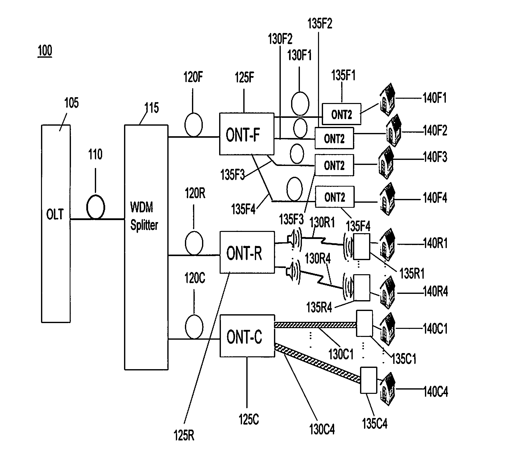
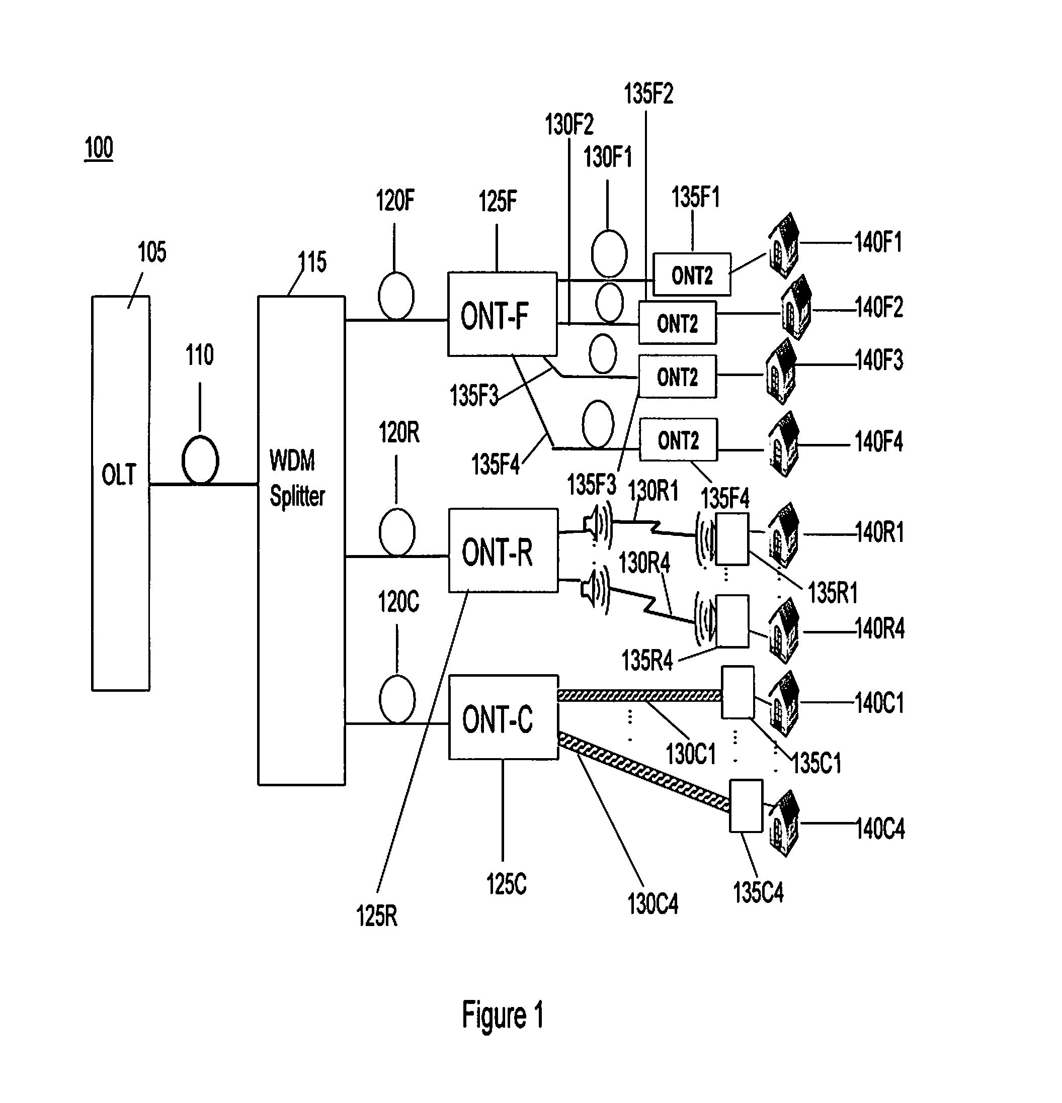
[0022]Referring to FIG. 1 a Passive Optical Network (PON) 100 is shown and which comprises an Optical Line Terminal (OLT) 105 coupled by an optical fibre 110 to a Wavelength Division Multiplex (WDM) splitter 115, and a number of Optical Network Terminals (ONT) 125F, 125R and 125C coupled to the WDM splitter using respective optical fibres 120E-120C. Each ONT 125F-C is coupled to a number of subscriber equipment 135F1-135F4, 135R1-135R2, and 135C1-135C2 respectively. These subscriber equipment may be coupled to their respective ONT using optical fibres 130F1-130F4, radio links 130R1-130R4, or copper cable 130C1-130C4. Each subscriber equipment may be installed within a respective subscribers premises 140F1-140C4 to service a number of communications appliances such as telephones, computers, or televisions. Alternatively one or more of the subscriber equipment may support communications appliances in a number of subscriber's premises.

[0023]It can be seen that, compared with known PON ...


PUM


Abstract

An optical network terminal (ONT) for use in an optical access network and comprising: an optical transceiver arranged to communicate with an optical line terminal using a wavelength which is modulated to carry sub-channels; a second transceiver arranged to communicate with a number of subscriber equipment using respective subscriber equipment channels; the ONT arranged to automatically map each subscriber equipment channel to a respective sub-channel of the wavelength without using an address associated with the respective subscriber equipment.

Description

FIELD OF THE INVENTION[0001]The present invention relates to Optical Access Networks such as Passive Optical Networks (PON), and nodes used within these networks such as Optical Network Terminals (ONT) and subscriber equipment.BACKGROUND OF THE INVENTION[0002]Passive Optical Networks (PON) are point-to-multipoint optical fibre based access networks. Traditionally, one or more preliminary optical fibres extend from an optical line terminal (OLT) which is coupled to a core or backhaul network. The optical fibre or fibres terminate at a power splitter from which further optical fibres extend. These further or secondary optical fibres may in turn terminate at further power splitters with tertiary optical fibres extending from these splitters and so on. In this way, a number of subscriber equipment may be coupled to the OLT by this network of optical fibres and splitters. Because the primary fibre or fibres adjacent the OLT are common to all of the subscriber equipment, this bandwidth re...

Claims


Application Information

Patent Timeline
Patent Type & Authority Applications(United States)
IPC IPC(8): H04J14/00
CPCH04J14/0226H04J14/0282H04J14/025H04J14/0246H04J14/0247H04J14/0298
Inventor GHIGGINO, PIERPAOLOCAVALIERE, FABIO
Owner TELEFON AB LM ERICSSON (PUBL)
Why Eureka
Try Eureka