

Drive device
- Summary
- Abstract
- Description
- Claims
- Application Information
AI Technical Summary
Benefits of technology
Problems solved by technology
Method used
Image

Examples
Embodiment Construction
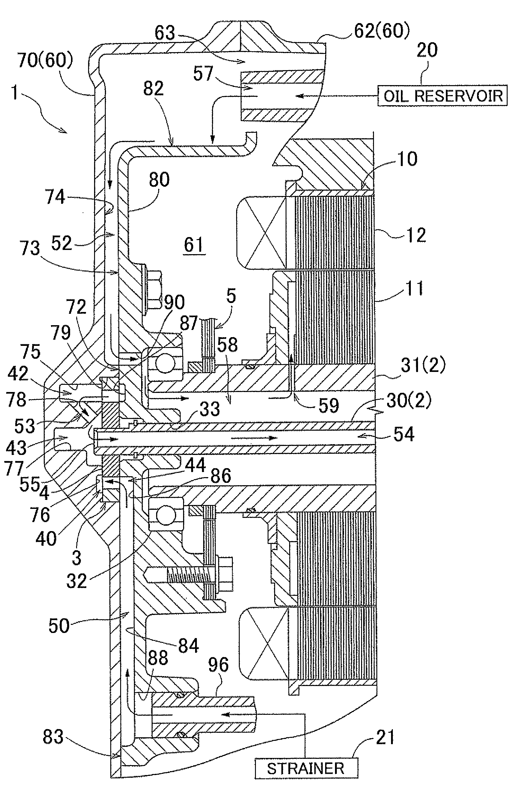
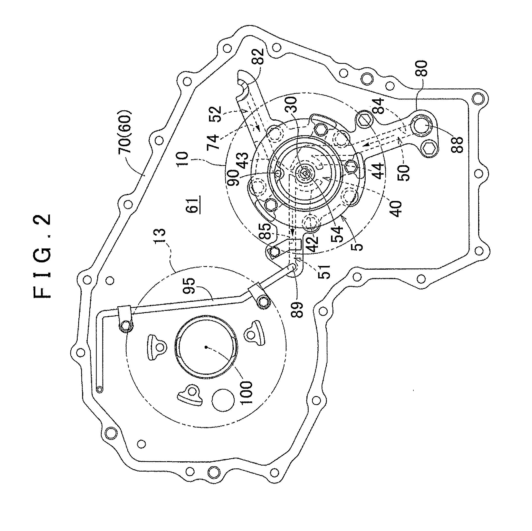
[0030]An embodiment of the present invention will be described below with reference to the accompanying drawings, with respect to an example in which the present invention is applied to a drive device for hybrid vehicles. As shown in FIG. 1, a drive device 1 of the present embodiment has an oil pump 3 in a cover portion 70 of a case 60 for accommodating a driving force transfer mechanism 2. The drive device 1 is characterized in the structure of the oil pump 3 provided in the cover portion 70, and the structure of oil passages associated with the oil pump 3. The structure of the drive device 1 of the present embodiment will be sequentially described in detail below in the sections “Overall Structure of Drive Device,”“Structure of Cover Portion,”“Structure of Pump Cover,”“Structure of Oil Pump,” and “Structure of Oil Passages.” Note that, in the following description, the “axial direction,” the “circumferential direction,” and the “radial direction” are defined based on the central a...
PUM
 Abstract
Description
Claims
Application Information