Apparatus And Method To Facilitate Wireless Uplink Resource Allocation

a wireless uplink and resource allocation technology, applied in the field of communication, can solve the problems of static ffr becoming grossly inefficient, static ffr typically requiring a priori network frequency planning, etc., and achieve the effect of improving system capacity and/or coverag

Inactive Publication Date: 2011-03-31
ALCATEL LUCENT SAS
View PDF5 Cites 56 Cited by
  • Summary
  • Abstract
  • Description
  • Claims
  • Application Information

AI Technical Summary

Benefits of technology

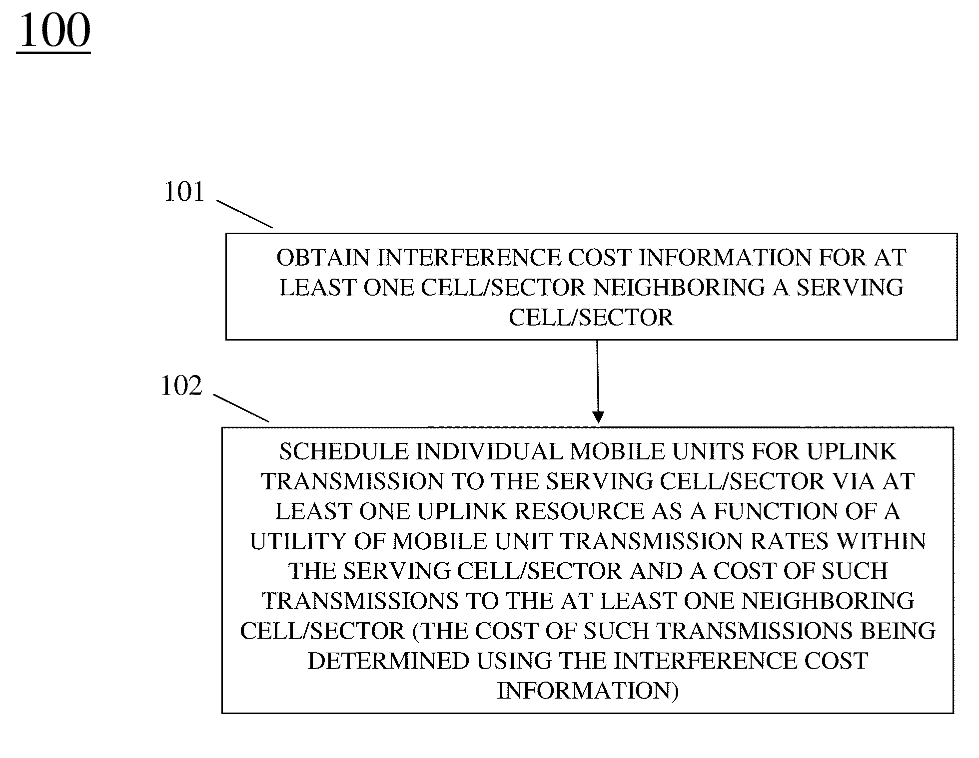
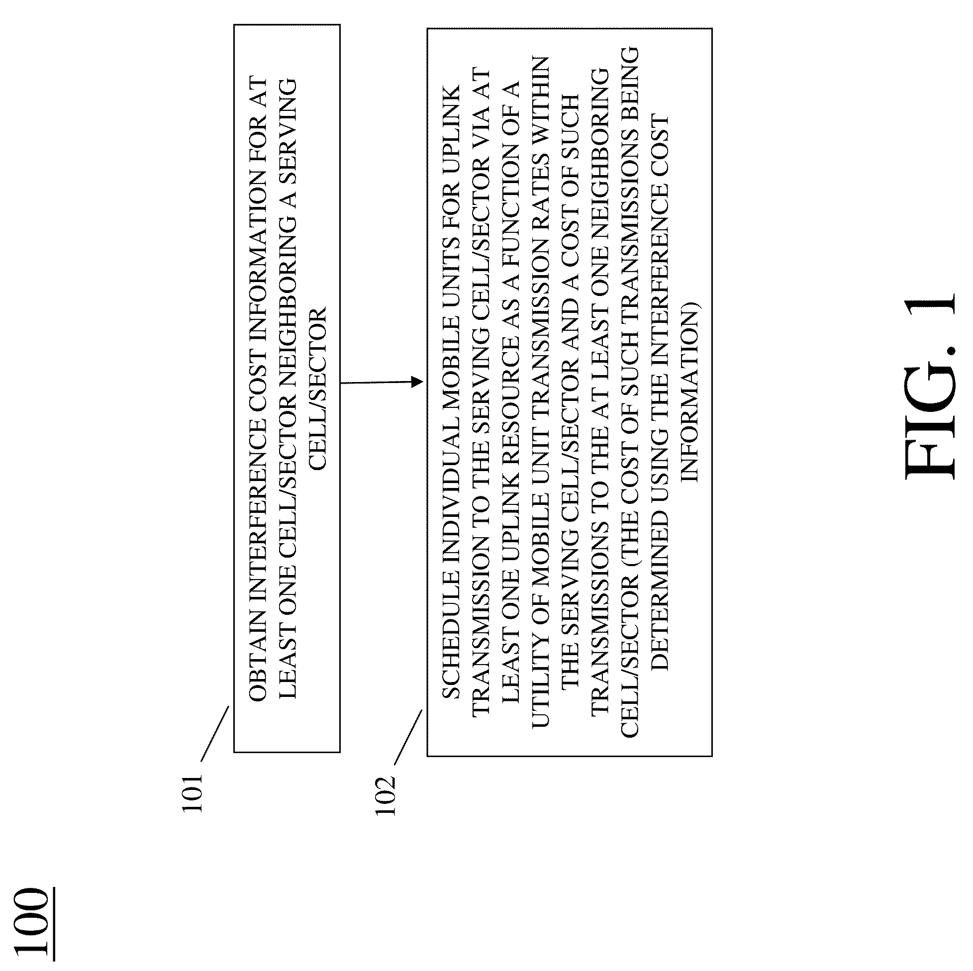
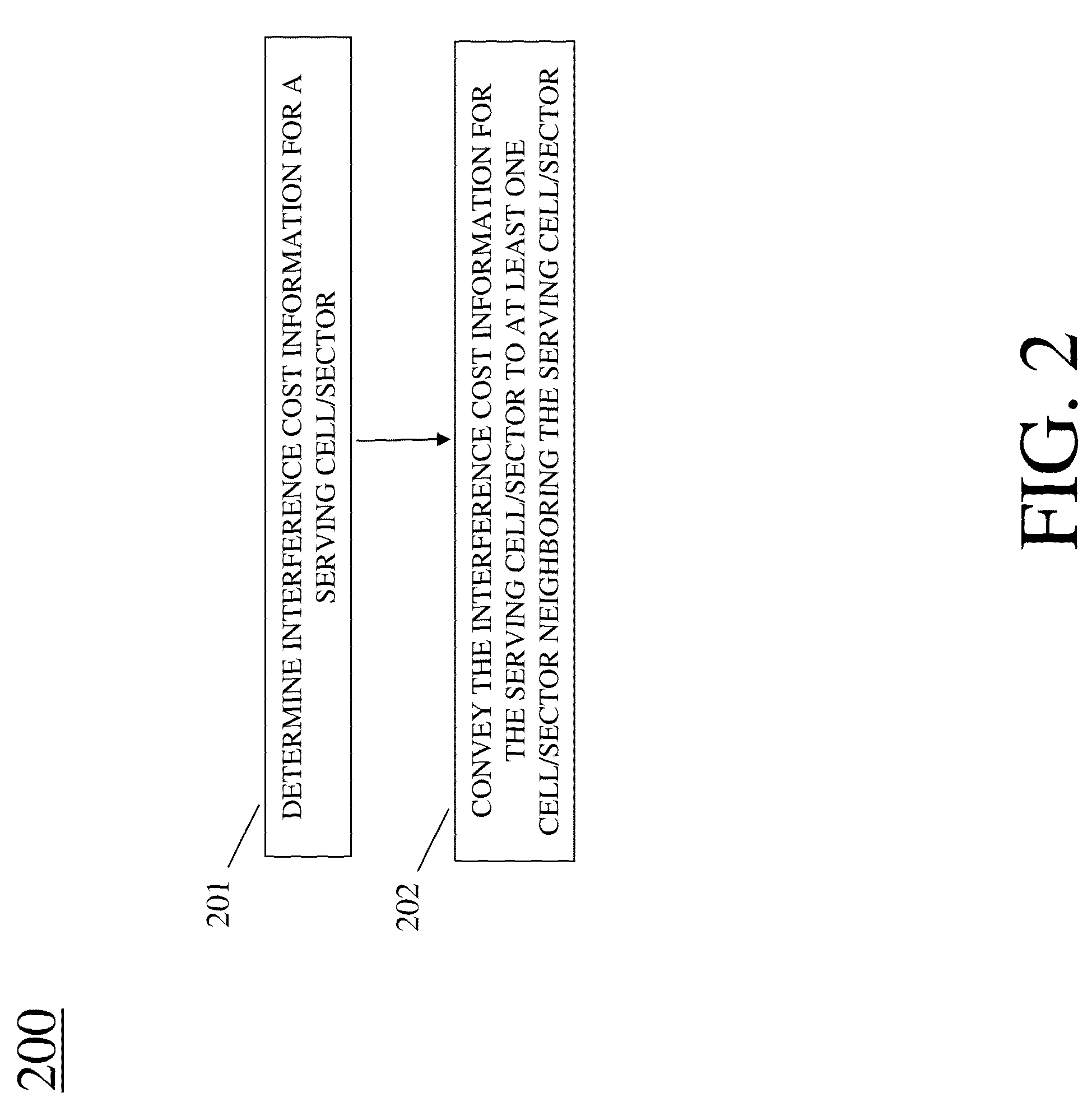
[0011]To address the need to improve system capacity and / or coverage, methods such as those depicted in diagrams 100 and 200 of FIGS. 1 and 2 may be employed. In one method, interference cost information is obtained (101) for at least one cell / sector neighboring a serving cell / sector. Individual mobile units are then scheduled (102) for uplink transmission to the serving cell / sector via at least one uplink resource as a function of a utility of mobile unit transmission rates within the serving cell / sector and a cost of such transmissions to the at least one neighboring cell / sector. Here, the cost of such transmissions to the at least one neighboring cell / sector is determined using the interference cost information. In another, or perhaps additional, method, interference cost information is determined (201) for the serving cell / sector. This interference cost information is conveyed (202) to at least one cell / sector neighboring the serving cell / sector.

Problems solved by technology

The problem is: how should system cells (or sectors) allocate mobile units to the bands, how to schedule mobile transmissions over time, and how to choose mobile transmit powers so that the system capacity and coverage are maximized.
The best static FFR solutions are non-adaptive: this means that if a system layout or user distribution changes (the latter typically happens at least several times a day), the static FFR can become grossly inefficient.
Furthermore, static FFR typically requires a priori network frequency planning.

Method used


Image

  • Apparatus And Method To Facilitate Wireless Uplink Resource Allocation
  • Apparatus And Method To Facilitate Wireless Uplink Resource Allocation
  • Apparatus And Method To Facilitate Wireless Uplink Resource Allocation

Examples


example embodiment

[0060]FIG. 4 is a block diagram depiction of a communication system in accordance with some specific embodiments of the present invention. Note that the frequency band is divided into j subbands and base stations (BSs) 1-3 are depicted in diagram 400. Regarding interference costs, each BS k continuously estimates the sensitivities a of its utility U to the interference I it receives in subband j:

aj(k)=∂U(k) / ∂Ij(k)

Done along with transmit scheduling below, updates of these costs are signaled to its respective neighbors.

[0061]Transmit power optimization involves using average propogation gains G, from users i to neighbor BSs 1, each BS k determines per-user i, per-subband j optimal transmit power (if scheduled) according to:

Pij=arg max[Hij≡U′i(Xi)Rij(Pij)−Σl≠kaj(l)Gi(l)Pij]

Note that transmit powers P change slowly.

[0062]Transmit scheduling is done independently by each BS k according to instantaneous scheduling weights

Ĥij≡U′i(Xi){circumflex over (R)}ij(Pij)−Σl≠kaj(l)Gi(l)Pij

along wi...


PUM


Abstract

Embodiments are described herein to provide an efficient, adaptive and distributed approach to wireless resource allocation that seeks to maximize system capacity and/or coverage on the reverse link. The general approach is for each cell (sector) base station to allocate (102) its mobile units to frequency subbands based on a local optimization objective. This objective takes into account the performance “costs” to the neighboring cells/sectors of transmissions by different mobile units in different subbands. An example of such an optimization objective can be the maximization of the “utility” of user transmission rates within the sector minus the cost of the transmissions to neighboring cells/sectors.

Description

FIELD OF THE INVENTION[0001]The present invention relates generally to communications and, in particular, to wireless uplink resource allocation in communication systems.BACKGROUND OF THE INVENTION[0002]Consider the reverse link (uplink) of a cellular system where available spectrum is divided into bands. Mobile units can be dynamically allocated to one of the bands or, more generally, to subsets of the bands. The problem is: how should system cells (or sectors) allocate mobile units to the bands, how to schedule mobile transmissions over time, and how to choose mobile transmit powers so that the system capacity and coverage are maximized. It is desirable to have solutions to such problems which involve minimal communication between base stations.[0003]One of the known solutions is fractional frequency reuse (FFR), where, for example, some of the frequency bands are used in all cells while other bands are used only in a subset of bands. This allows the system to place into separate ...

Claims


Application Information

Patent Timeline
Patent Type & Authority Applications(United States)
IPC IPC(8): H04B15/00H04W72/08H04B7/005
CPCH04W28/04H04W52/244H04W72/12H04W72/082H04W72/0453H04W72/541
Inventor STOLYAR, ALEKSANDRVISWANATHAN, HARISH
Owner ALCATEL LUCENT SAS
Why Eureka
Try Eureka