System, method and apparatus for electrosurgical instrument with movable suction sheath

a technology of electrosurgical instruments and suction sheaths, applied in the field of electrosurgical instruments, can solve the problems of insufficient fluid and debris removal of the treatment site of electrosurgical instruments with these types of aspiration systems, and the operating field is cluttered with tissue fragments,

Active Publication Date: 2011-03-31
ARTHROCARE
View PDF106 Cites 19 Cited by
  • Summary
  • Abstract
  • Description
  • Claims
  • Application Information

AI Technical Summary

Benefits of technology

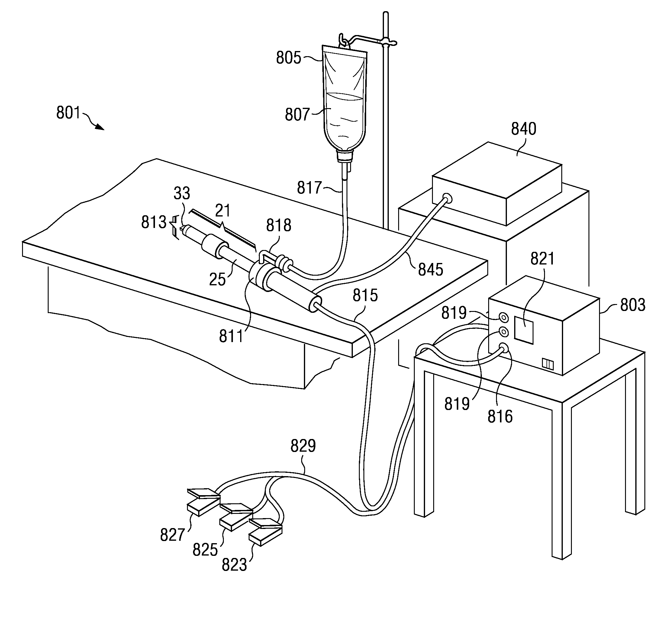
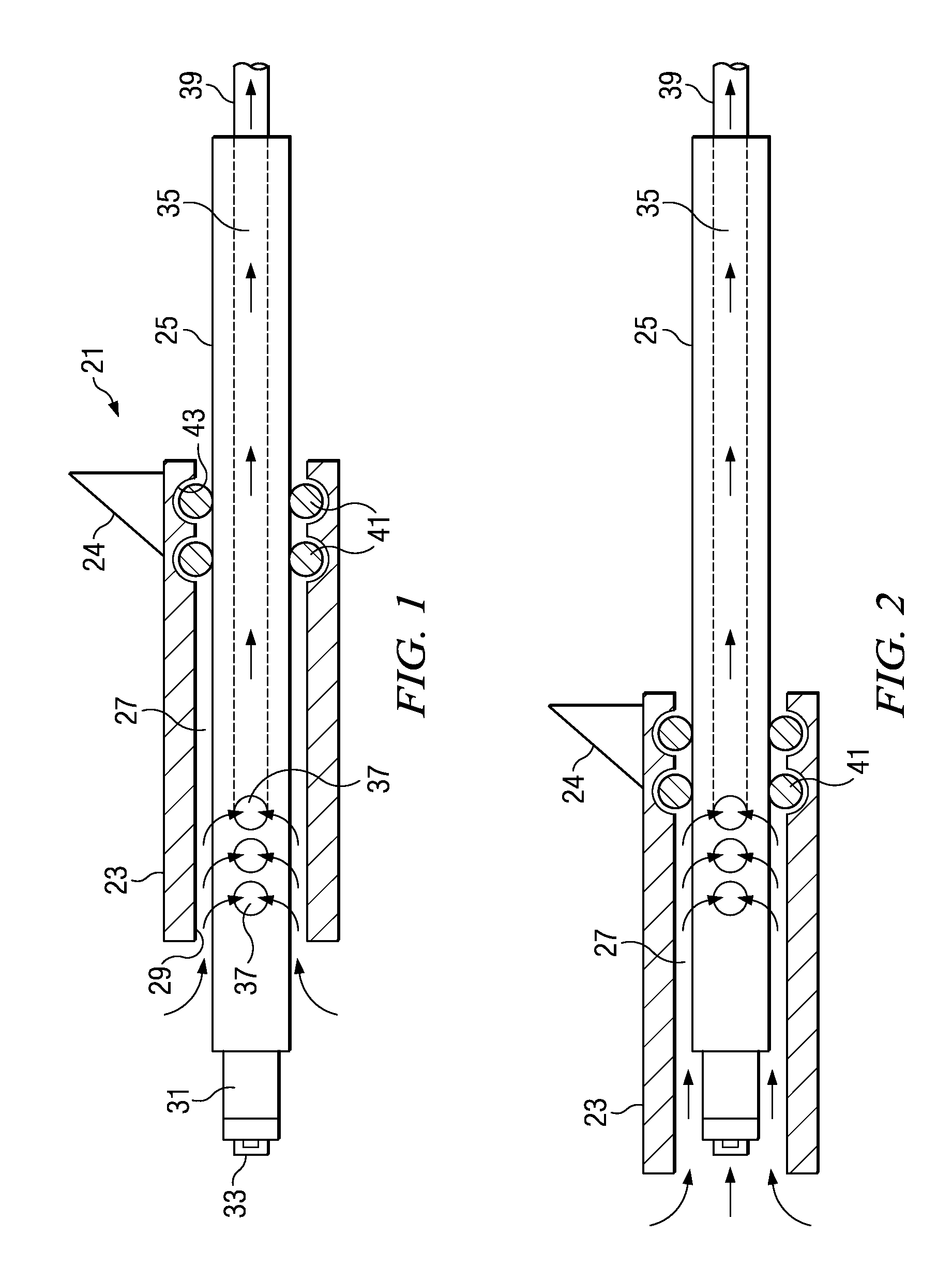
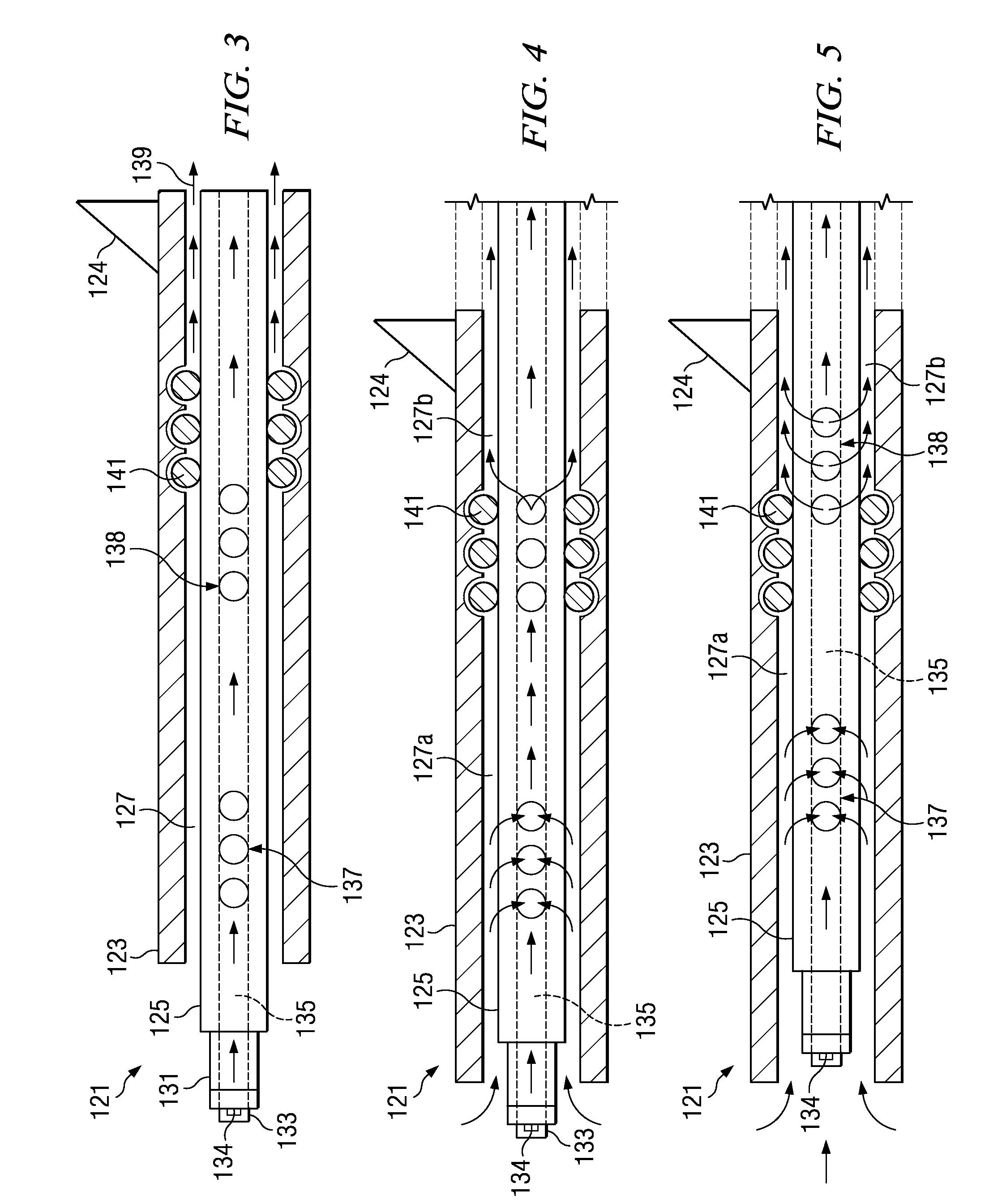
[0007]In another embodiment, the sheath assembly has a range of motion between the first and second positions that provides a variable level of fluid and debris removal. Preferably, the sheath assembly is movable to provide a minimal level of fluid and debris removal in the first position, to a maximum level of fluid and debris removal in the second position. The fluid aspiration element comprises an inner lumen extending through a portion of the shaft, and first and second plurality of ports extending radially through the shaft in fluid communication with the inner lumen. The first and second plurality of ports are preferably axially spaced apart. A vacuum source is connected to the inner lumen and to the outer lumen proximal to the radial seal. Aspiration is preferably provided only through an opening to the inner lumen at the distal end of the shaft when the sheath assembly is in the first position despite the outer lumen proximal the radial seals being under vacuum pressure, as the radial seal creates a bypass preventing aspiration through the outer lumen and first and second plurality of ports. When the sheath assembly is in an intermediate or second position, the vacuum source may provide a sequential suction path through the inner lumen as well as through the outer lumen that is distal to the radial seal, the first plurality of ports, and the second plurality of ports via the outer lumen proximal to the radial seal.
[0008]The invention may further comprise a method for treating tissue including the steps of positioning an active electrode adjacent to tissue; applying a first high frequency voltage between the active electrode and a return electrode; positioning a sheath assembly in a first position, the first position creating an aspiration region around the active electrode; aspirating fluid from the region adjacent to the active electrode; retracting the sheath assembly to a second position; advancing the active electrode into the tissue; applying a second high frequency voltage between the return electrode and a coagulation electrode; and returning the sheath assembly to the first position to aspirate fluid from a region axially spaced away from the active electrode.

Problems solved by technology

Conventional electrosurgical cutting or resecting devices tend to leave the operating field cluttered with tissue fragments that have been removed or resected from the target tissue.
For some applications, electrosurgical instruments with these types of aspiration systems provide insufficient fluid and debris removal from the treatment site.
Aspiration may be too slow because the aspiration rate is limited by the shaft size, or may be prone to clogging.
Although separate or additional aspiration systems may be employed for such applications, they add significant cost and complication to such procedures, while requiring multiple suctions lines and crowding of the surgical area.
Further, certain procedures may require aspiration of relatively large volumes of fluid from the target site, resulting in difficulties in generating and maintaining a plasma from the ionized electrically conductive fluid in the vicinity of the active electrode.

Method used


Image

  • System, method and apparatus for electrosurgical instrument with movable suction sheath
  • System, method and apparatus for electrosurgical instrument with movable suction sheath
  • System, method and apparatus for electrosurgical instrument with movable suction sheath

Examples


Embodiment Construction

[0017]Before the present invention is described in detail, it is to be understood that this invention is not limited to particular variations set forth herein as various changes or modifications may be made to the invention described and equivalents may be substituted without departing from the spirit and scope of the invention. As will be apparent to those of skill in the art upon reading this disclosure, each of the individual embodiments described and illustrated herein has discrete components and features which may be readily separated from or combined with the features of any of the other several embodiments without departing from the scope or spirit of the present invention. In addition, many modifications may be made to adapt a particular situation, material, composition of matter, process, process act(s) or step(s) to the objective(s), spirit or scope of the present invention. All such modifications are intended to be within the scope of the claims made herein.

[0018]Methods ...


PUM


Abstract

An electrosurgical instrument having active and return electrodes with a movable suction sheath for variable fluid and debris removal during surgical procedures is disclosed. The suction apparatus has an outer sheath that is external to a shaft to provide a lumen. The sheath assembly is axially movable relative to the fluid aspiration element between first and second positions for treating the target site and fluid and debris removal, respectively. The first position positions the distal end of the shaft axially distal to a leading edge of the sheath assembly. The second position positions the distal leading edge of the sheath assembly axially adjacent to the end of the shaft. The fluid aspiration element comprises an inner lumen extending through the shaft, and at least one port extending radially through the shaft. The port is in communication with the inner lumen. A vacuum provides suction through the port and inner lumen.

Description

TECHNICAL FIELD[0001]The present invention relates in general to electrosurgical instruments and, in particular, to an electrosurgical instrument with a fluid aspiration device for controllably removing fluid from a treatment site. More particularly, the present invention relates to a system, method and apparatus for an electrosurgical instrument having active and return electrodes with a movable suction sheath for variable fluid and debris removal during surgical procedures.DESCRIPTION OF THE RELATED ART[0002]In some electrosurgical procedures an instrument (see, e.g., U.S. Pat. Nos. 5,683,366 and 6,235,020, which are incorporated herein by reference) has an active electrode and a return electrode that are used to treat body tissue. Treatment with this instrument may include, for example, coagulation, cutting, ablating, abrading or puncturing the tissue. In various designs, a current path is created between the active and return electrodes, thereby generating a limited plasma field...

Claims


Application Information

Patent Timeline
Patent Type & Authority Applications(United States)
IPC IPC(8): A61B18/14
CPCA61B18/1402A61B2218/007A61B2018/1472A61B2018/00583
Inventor DAHLA, ROBERT H.GUTIERREZ, IRMA
Owner ARTHROCARE
Why Eureka
Try Eureka