Equipment and Methods for Deploying Line in a Wellbore

a wellbore and equipment technology, applied in the direction of directional drilling, drilling holes/well accessories, sealing/packing, etc., can solve the problem that the line from the second reel may also be unwound, and achieve the effect of minimizing the stress on the lin

Inactive Publication Date: 2011-04-07
SCHLUMBERGER TECH CORP
View PDF12 Cites 31 Cited by
  • Summary
  • Abstract
  • Description
  • Claims
  • Application Information

AI Technical Summary

Benefits of technology

[0015]The first aspect of the invention is a system for deploying line in a subterranean wellbore. It preferably comprises three principal elements. The first element is a device that travels down a tubular body inside the subterranean wellbore. In the present application, the first element is presented as a wiper plug; however, those skilled in the art will appreciate that other devices such as sondes, darts, balls, canisters, bombs and the like would be equally appropriate. The second element is a first apparatus for dispensing line, comprising a first reel of line. The line is preferably attached to the wiper plug, and is able to be unwound from the first reel of the first apparatus as process fluid is pumped into the tubular body and the wipe...

Problems solved by technology

The second apparatus is installed at a location away from the device; however, line...

Method used


Image

  • Equipment and Methods for Deploying Line in a Wellbore
  • Equipment and Methods for Deploying Line in a Wellbore
  • Equipment and Methods for Deploying Line in a Wellbore

Examples


Embodiment Construction

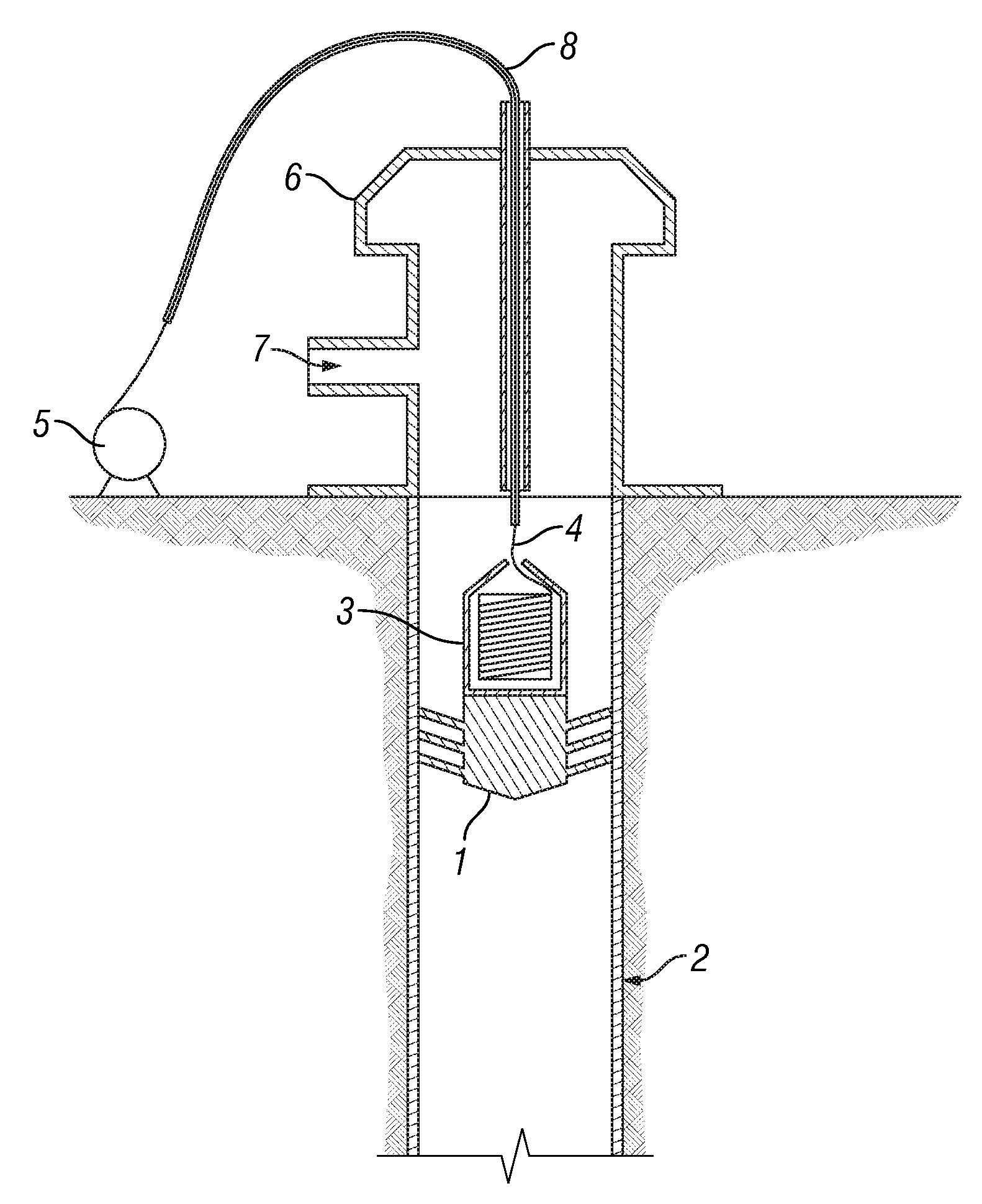
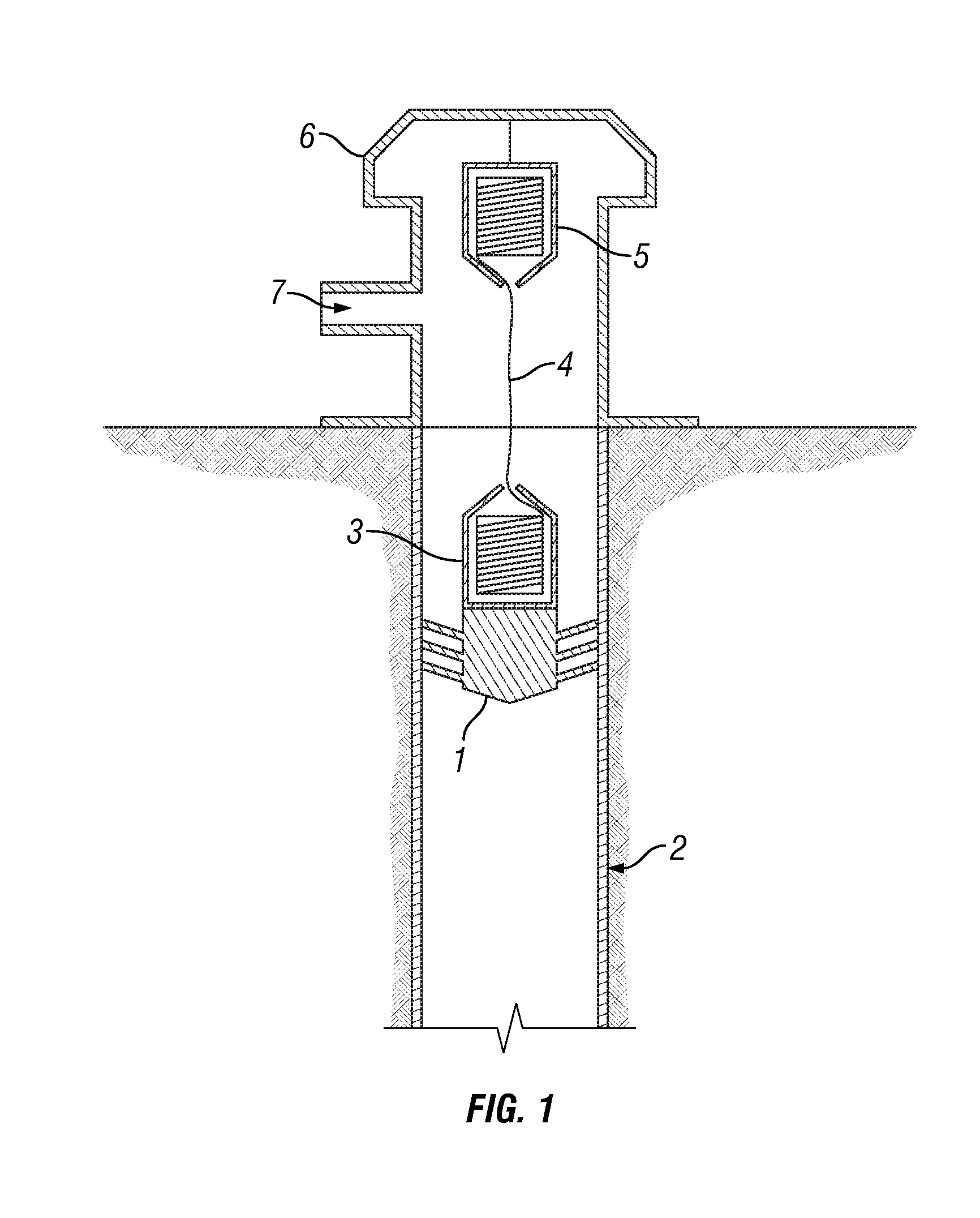
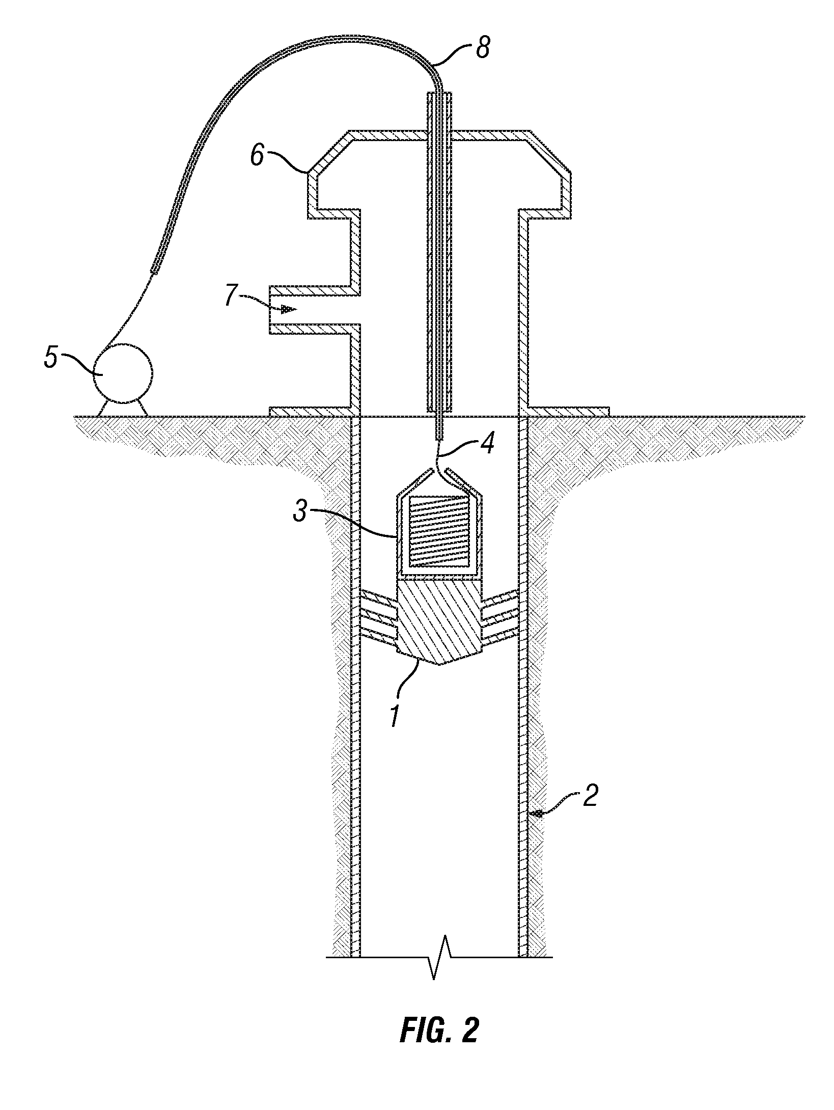
[0028]The invention may be described in terms of treatment of vertical wells, but is equally applicable to wells of any orientation. The invention may be described for hydrocarbon production wells, but it is to be understood that the invention may be used for wells for production of other fluids, such as water or carbon dioxide or, for example, for injection or storage wells. This invention may be described for offshore and land wells. It should also be understood that throughout this specification, when a concentration or amount range is described as being useful, or suitable, or the like, it is intended that any and every concentration or amount within the range, including the end points, is to be considered as having been stated. Furthermore, each numerical value should be read once as modified by the term “about” (unless already expressly so modified) and then read again as not to be so modified unless otherwise stated in context. For example, “a range of from 1 to 10” is to be ...


PUM


Abstract

The invention is related in general to wellbore-telemetry technology. In particular, the invention relates to improved equipment and methods for deploying line in a wellbore. A continuous line is dispensed from two apparatuses. One apparatus is attached to a device such as a wiper plug that travels through a tubular body such as casing. The other apparatus is fixed either inside or outside a wellhead. As a process fluid is pumped into the tubular body, forcing the first apparatus and the device through the tubular body, line may unfurl from the first apparatus, the second apparatus, or both. In this way, stress on the line during deployment is minimized.

Description

BACKGROUND OF THE INVENTION[0001]The statements in this section merely provide background information related to the present disclosure and may not constitute prior art.[0002]The invention is related in general to wellbore-telemetry technology. In particular, the invention relates to improved equipment and methods for deploying line in a wellbore. Those skilled in the art will appreciate that the term “line” is applicable to fiber, wire, rope and the like. In addition, a line may comprise one or more strands of material.[0003]In recent years, the deployment of fiber lines in subterranean wellbores has become increasingly frequent. The most common application is to install optical fiber as a conduit through which various downhole measurements may be performed. Such measurements include temperature, pressure, pH, density, resistivity, conductivity, salinity, carbon dioxide concentration, asphalene concentration, etc. Today, optical fiber technologies may be employed throughout the lif...

Claims


Application Information

Patent Timeline
IPC IPC(8): E21B19/00E21B23/03
CPCE21B23/08E21B47/123E21B33/16E21B23/14E21B47/135
Inventor GAMBIER, PHILIPPE
Owner SCHLUMBERGER TECH CORP
Why Eureka
Try Eureka