Transmission mechanism having deceleration function

a technology of transmission mechanism and deceleration function, which is applied in the direction of gearing details, braking systems, gearing, etc., can solve the problems of motor still having to overcome the resistance of springs, the guide screw cannot be self-locked, and the user's discomfort, so as to avoid melting phenomenon, reduce frictional heat, and excellent transmission performance

Active Publication Date: 2011-04-07
TIMOTION TECH CO LTD
View PDF10 Cites 14 Cited by
  • Summary
  • Abstract
  • Description
  • Claims
  • Application Information

AI Technical Summary

Benefits of technology

[0012]Since of following functions and merits, the invention has small frictional heat without the tendency to generate heat, such that the melting phenomenon is avoided. It is easy for the intermediary ring to rotate in the isolator, making the transmission mechanism have an excellent transmission performance. When the guide screw is pushed backward, there is no relative transmission generated among the intermediary ring, each needle roller, the passive sleeve and the guide screw, whereby the guide screw is fixed firmly and it can effectively prevent both the guide screw and the nut from incurring a self-sliding phenomenon. Following the increase of the load, the frictional force between each transmission components is increased, so there is no unnecessary frictional force generated and there is no energy consumed when there is no load. The retracting speed of the telescopic tube is substantially equal, even under different loads. So, the declining speed can be kept constant, increasing the using comfort of user significantly.

Problems solved by technology

However, there are two problems arisen subsequently.
First of all, the guide screw is unable to be self-locked.
Secondly, the declining speed of the nut engaged with the guide screw and the telescopic tube connected to the nut is too fast, causing an uncomfortable problem to the user.
This means that the motor still has to overcome the resistance of spring, when a retraction is occurred.
So, it is still needed to consume energy, even when there is no load, causing an unnecessary waste of energy, which is a drawback needed to be solved urgently.

Method used


Image

  • Transmission mechanism having deceleration function
  • Transmission mechanism having deceleration function
  • Transmission mechanism having deceleration function

Examples


Embodiment Construction

[0023]In cooperation with attached drawings, the technical contents and detailed description of the present invention are described thereinafter according to a number of embodiments, not used to limit its executing scope. Any equivalent variation and modification made according to appended claims is all covered by the claims claimed by the present invention.

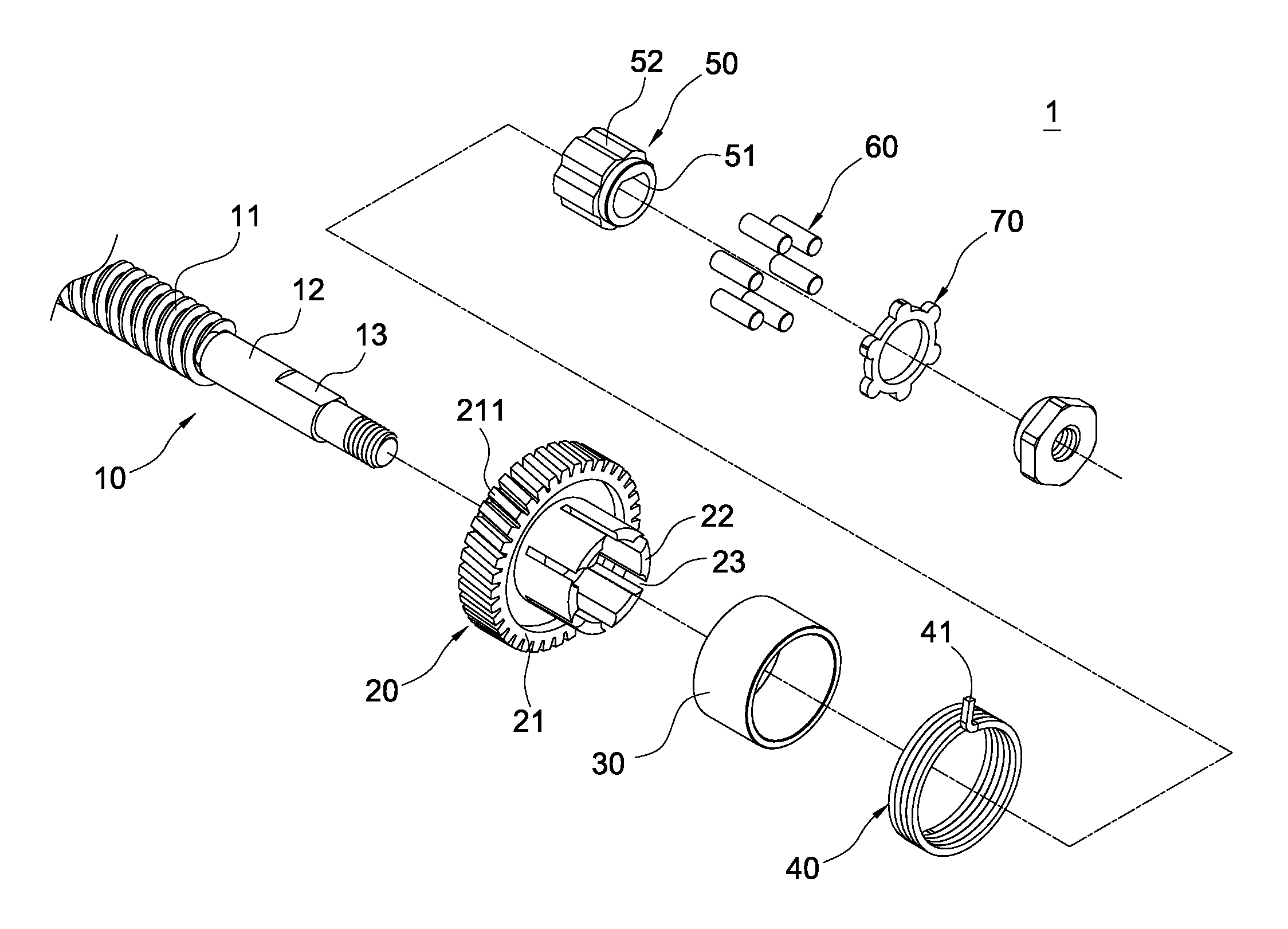
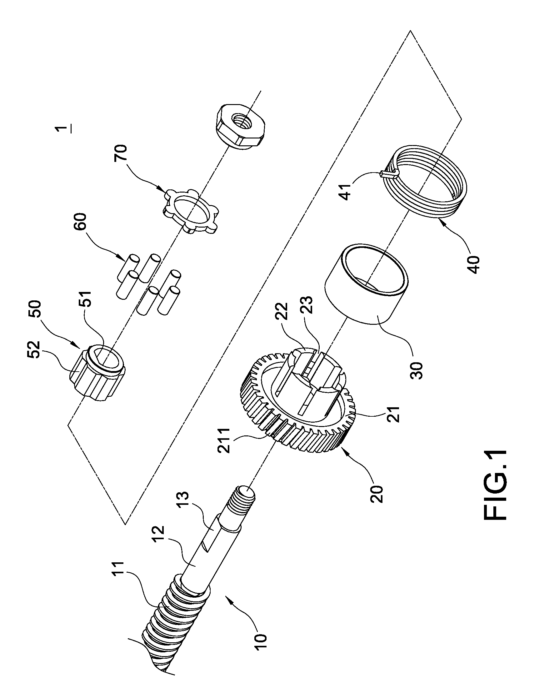
[0024]As shown in FIG. 1, the invention is to provide a transmission mechanism having deceleration function. This transmission mechanism 1 mainly includes a guide screw 10, a worm wheel set 20, an intermediary ring 30, an isolator 40, a passive sleeve 50 and a plurality of needle rollers 60.

[0025]The guide screw 10 has a threaded section 11 and an axial section 12 extended from the threaded section 11. In the meantime, an external plane 13 is arranged at one side of the axial section 12. According to a practical requirement of transmission, this guide screw can be arranged as a left-hand rotation or a right-hand rotation. In this...


PUM


Abstract

A transmission mechanism having deceleration function includes a guide screw, a worm wheel set, an intermediary ring, an isolator and a passive sleeve. The worm wheel set is fitted onto the guide screw and includes worm wheel and plural claw arms. A spacing slot is formed between any two adjacent claw arms. The intermediary ring is fitted onto a peripheral edge of each claw arm. The isolator surrounds a peripheral edge of the intermediary ring with one side fixed to an actuator. With plural grooves arranged on a peripheral edge thereof, the passive sleeve is fitted onto the guide screw. An accommodation space is formed among the groove, spacing slot and intermediary ring. Each needle roller is accommodated in the accommodation space and inter-contacted with the claw arm, the intermediary ring and the passive sleeve. By frictional function, a rotation of the guide screw in a specific direction is hindered to reach a deceleration purpose.

Description

BACKGROUND OF THE INVENTION[0001]1. Field of the Invention[0002]The present invention in general relates to a transmission mechanism, in particular, to a transmission mechanism for linear actuator.[0003]2. Description of Prior Art[0004]Linear actuator is mainly to use a plurality of driving assemblies, for example, motor, worm and worm wheel, to rotate a guide screw. In the meantime, a telescopic tube is engaged with the guide screw and is driven thereby to generate the linear motions of stretch and retraction. Since of many superior conditions, for example, simplicity and convenience, to those of air / oil pressure cylinders in terms of structure and arrangement, the linear actuator has been comprehensively applied to the facilities of hospital bed and electric chair or other occasions needed the operations of stretch and retraction.[0005]According to prior arts, in order to increase mechanism efficiency or possess faster moving speed, it usually has to enlarge the guide route of the...

Claims


Application Information

Patent Timeline
Patent Type & Authority Applications(United States)
IPC IPC(8): F16D67/00F16H57/00
CPCF16H25/2454F16H2025/2084Y10T74/18792Y10T74/18704F16H2025/209
Inventor TSENG, KUAN-SHU
Owner TIMOTION TECH CO LTD
Why Eureka
Try Eureka