Apparatus for Producing Reconfigurable Walls of Water

a technology of apparatus and water maze, which is applied in the direction of spray nozzles, amusements, theatre/circus, etc., can solve the problems of inability to achieve the structure of an outer wall and a maze, and achieve the effect of reducing or eliminating the need for vertical supports, array of spray bars, and facilitating the reconfiguration of the maz

Active Publication Date: 2011-04-07
TECHNIFEX PRODS
View PDF15 Cites 2 Cited by
  • Summary
  • Abstract
  • Description
  • Claims
  • Application Information

AI Technical Summary

Benefits of technology

[0010]Another embodiment of the invention provides an apparatus for producing the third type of water maze in which falling water is used to define the walls of a maze and facilitating the reconfiguration of the maze while substantially reducing or eliminating the need for upright supports within the “shadow” of the array of spray bars, i.e. the area directly below the array of spray bars. The apparatus includes an array of spray bars and an array of valves that can be used to activate and deactivate spray bars so as to define a maze and subsequently reconfigure the maze. Further, the apparatus includes a hanger system for suspending at least the array of spray bars from an overhead support. While some kind of vertical support structure is associated with the overhead support, this vertical support structure can typically be located adjacent to the periphery of the maze or spaced from the periphery of the maze, thereby reducing or at least substantially eliminating in many instances the need for an array of upright supports within the shadow of the array of spray bars to hold up the array of spray bars. By suspending the array of spray bars from an overhead support, it is feasible to locate the array of water valves and one or more water manifolds that supply water to the valves a substantial distance away from the array of spray bars. With such an arrangement, water lines can be run from the valves to the spray bars with the water lines coming in from the side of the array of spray bars, thereby reducing or eliminating the need for vertical supports located in the “shadow” of the array of spray bars to carry or support water supply lines for the spray bars.
[0011]In one embodiment, the ability to suspend the array of spray bars from an overhead support and avoid the use of upright supports for the array of spray bars is enhanced by the use of a spray bar that is lightweight and retains a relatively small amount of water during operation. As such, the cumulative weight of the spray bar and of the water resident in the spray bar during operation is relatively low, thereby reducing the load per unit area on the overhead structure relative to heavier spray bars and / or spray bars that retain relatively large amounts of water during operation.
[0013]In certain situations, it may be desirable to locate a water valve immediately adjacent to the spray bar with which the valve is associated. For example, locating the valve in this manner may reduce the amount of water that is expelled from a spray bar when the valve is switched from providing water to the spray bar to not providing water to the spray bar relative to another location for the valve. It may also be desirable in certain situations to associate a sub-water manifold (i.e., a portion of an overall water manifold that supplies water to the entire array of spray bars) with a subset of the array of spray bars to simplify the piping connections that need to be made between the source of water and the subset of the array of spray bars. As such, in other embodiments, the hanger system supports the array of spray bars, the array of water valves, and potentially one or more sub-water manifolds.
[0016]Another embodiment of the kit includes a plurality of substantially identical spray bars, a plurality of substantially identical spray bar connecting devices that are each capable of connecting a sub-group of the plurality spray bars to one another, and a plurality of substantially identical valves for use in controlling the flow of water to the plurality of spray bars. However, in this embodiment, the kit includes a plurality of modules that each includes a combination of one or more spray bars, one or more spray bar connecting devices, and one or more valves. In one embodiment, a module is comprised of a plurality of spray bars and a plurality of spray bar connecting devices that join the plurality of spray bars to one another. For example, if the corners of the spray bars are 90° / 270° type and the bracket system of a spray bar connector is capable of engaging up to four spray bars, one module may be comprised of a sufficient number of spray bars and sufficient number of spray bar connectors to form a 2×2 grid array of spray bars. The use of such a module can significantly reduce the on-site assembly time of a maze apparatus. In another embodiment, a module is comprised of a spray bar and one or more valves that each engages the spray bar.

Problems solved by technology

A maze comprised of an outer wall but with no inner wall structure is feasible.
However, as such a maze become more complex, it typically becomes more efficient to adopt a maze structure that is comprised of an outer wall and an inner wall structure.

Method used


Image

  • Apparatus for Producing Reconfigurable Walls of Water
  • Apparatus for Producing Reconfigurable Walls of Water
  • Apparatus for Producing Reconfigurable Walls of Water

Examples


Embodiment Construction

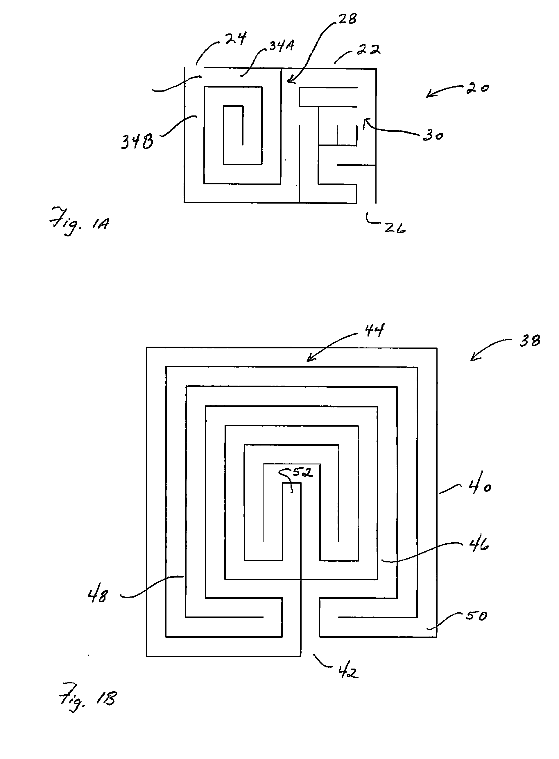
[0033]A maze is a structure comprised of an outer wall that encloses an area and, in many cases, an inner wall structure that is located within the enclosed area. The outer wall and the inner wall structure define a path between an entrance and an exit that are each associated with the outer wall. The path is the area within the outer wall that is not part of any inner wall structure and over which a player is allowed to move or navigate. Characteristic of a maze is at least one complex branch, i.e., a point at which two or more passageways of the path intersect and the solver of the maze is confronted with a decision as to which of two or more passageways is to be taken. FIG. 1A is an example of a maze 20. The maze 20 includes an outer wall 22 that encloses an area. Associated with the outer wall are an entrance 24 at which a player enters the maze and an exit 26 at which a player that has successfully negotiated the maze exits the maze. While the entrance 24 and the exit 26 are de...


PUM


Abstract

The present invention is directed to an apparatus for producing a water maze from walls of falling water that can be reconfigured to change the maze. In one embodiment, the apparatus is comprised of a plurality of spray bars that are each capable of producing a separate wall of falling water droplets and a plurality of water valves that are each associated with only one spray bar. The water valves can be used to define at least two different paths between the entrance and exit of the maze. The apparatus is also capable of being used to create interesting visual effects by projecting light / images on to multiple screens created by walls of falling water droplets.

Description

FIELD OF THE INVENTION[0001]The present invention relates to an apparatus for producing a reconfigurable water maze and capable of being adapted to produce visual effects in which light engages one or more walls of water.BACKGROUND OF THE INVENTION[0002]A maze is a structure that includes an outer wall that encloses an area and typically includes an inner wall structure that is located within the enclosed area. The outer wall and inner wall structure define a path between an entrance and an exit associated with the outer wall. The path being the portion of the maze that is within the outer wall that is not part of the inner wall structure and over which a solver of the maze is allowed to move or navigate. Characteristic of a maze is at least one complex branch, i.e., a point at which two or more passageways of the path intersect and the solver of the maze is confronted with a decision as to which of two or more passageways is to be taken. Further, in most mazes, the entrance and exi...

Claims


Application Information

Patent Timeline
Patent Type & Authority Applications(United States)
IPC IPC(8): B05B1/14
CPCB05B1/20A63J11/00B05B17/085A63G31/007B05B17/08
Inventor LUNDE, MONTGOMERY C.FOLCKEMER, CLEMENT
Owner TECHNIFEX PRODS
Why Eureka
Try Eureka