

Rotational angle sensing device
- Summary
- Abstract
- Description
- Claims
- Application Information
AI Technical Summary
Benefits of technology
Problems solved by technology
Method used
Image

Examples
first embodiment
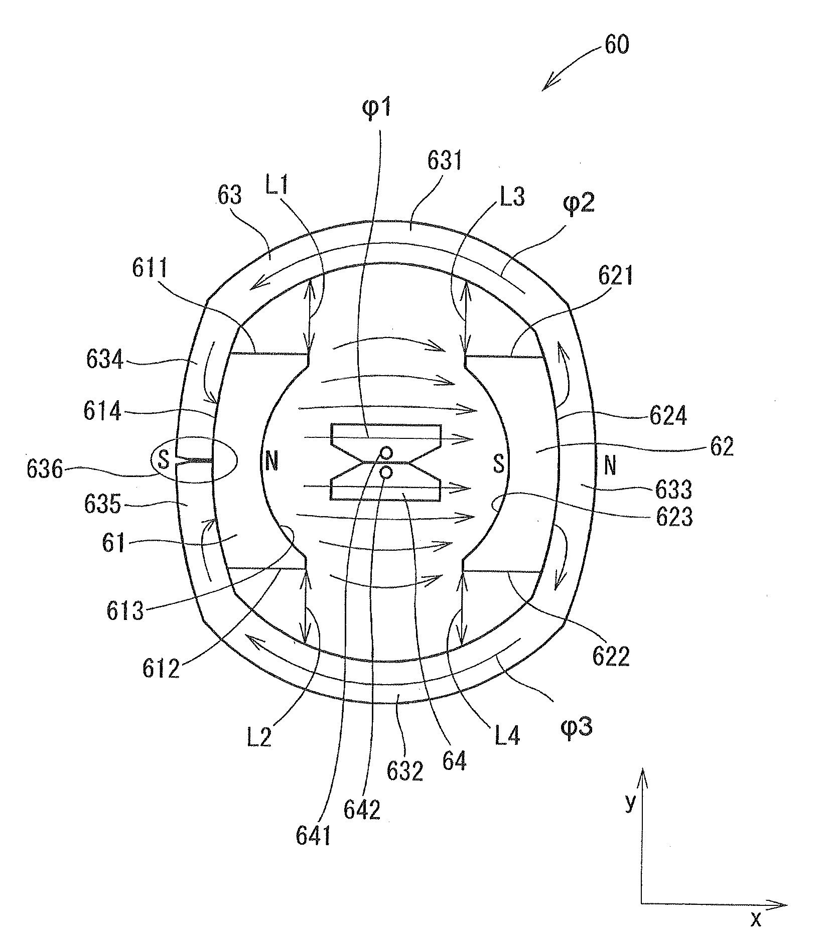
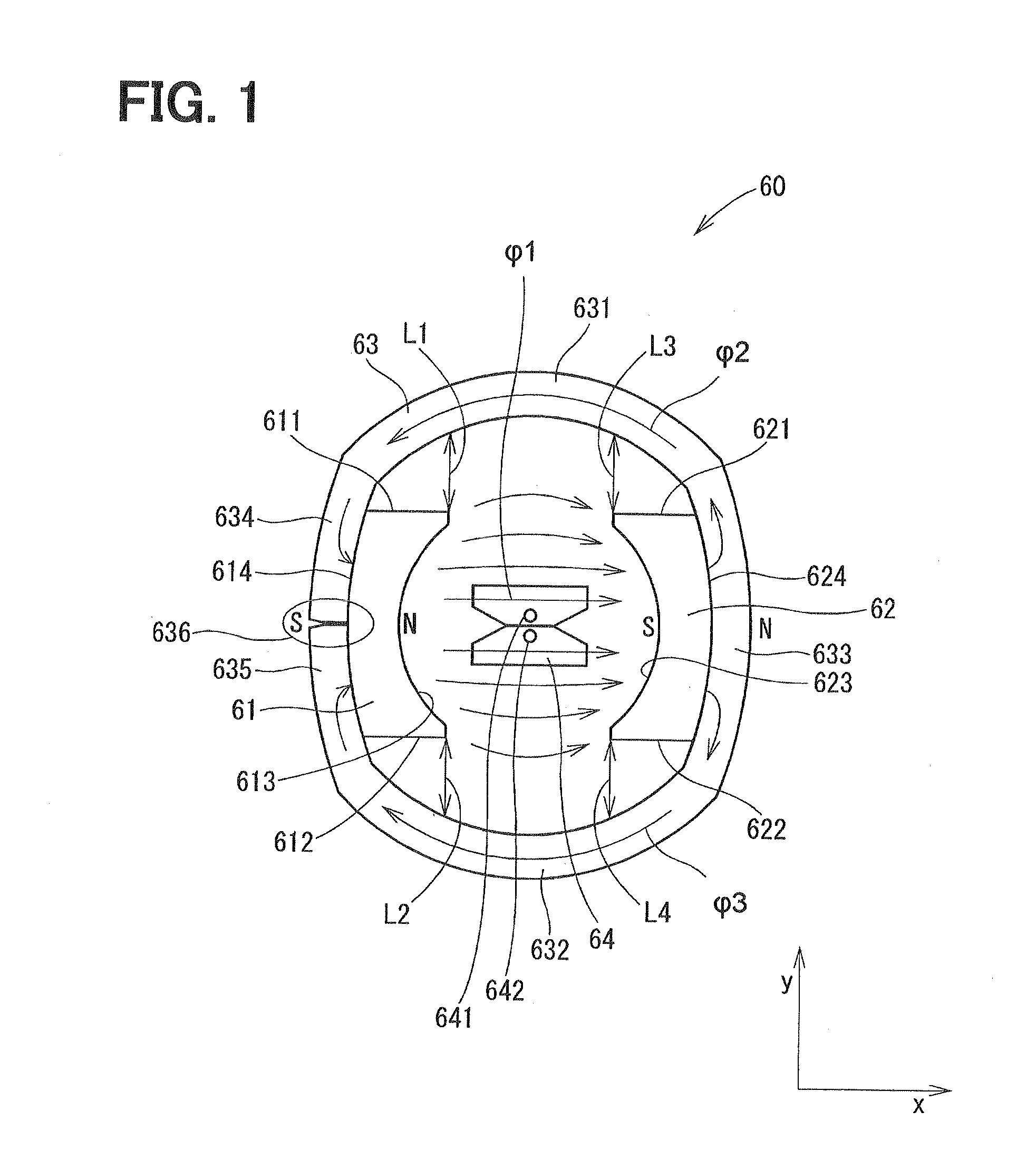
[0019]A rotational angle sensing device, which is applied to an accelerator pedal module, according to a first embodiment of the present invention will be described. The accelerator pedal module senses an amount of depression of an accelerator pedal and outputs the sensed amount of depression of the accelerator pedal as a voltage signal, which indicates a rotational angle of the accelerator pedal. An engine control unit (EDU) controls an operational state of an internal combustion engine based on this voltage signal.
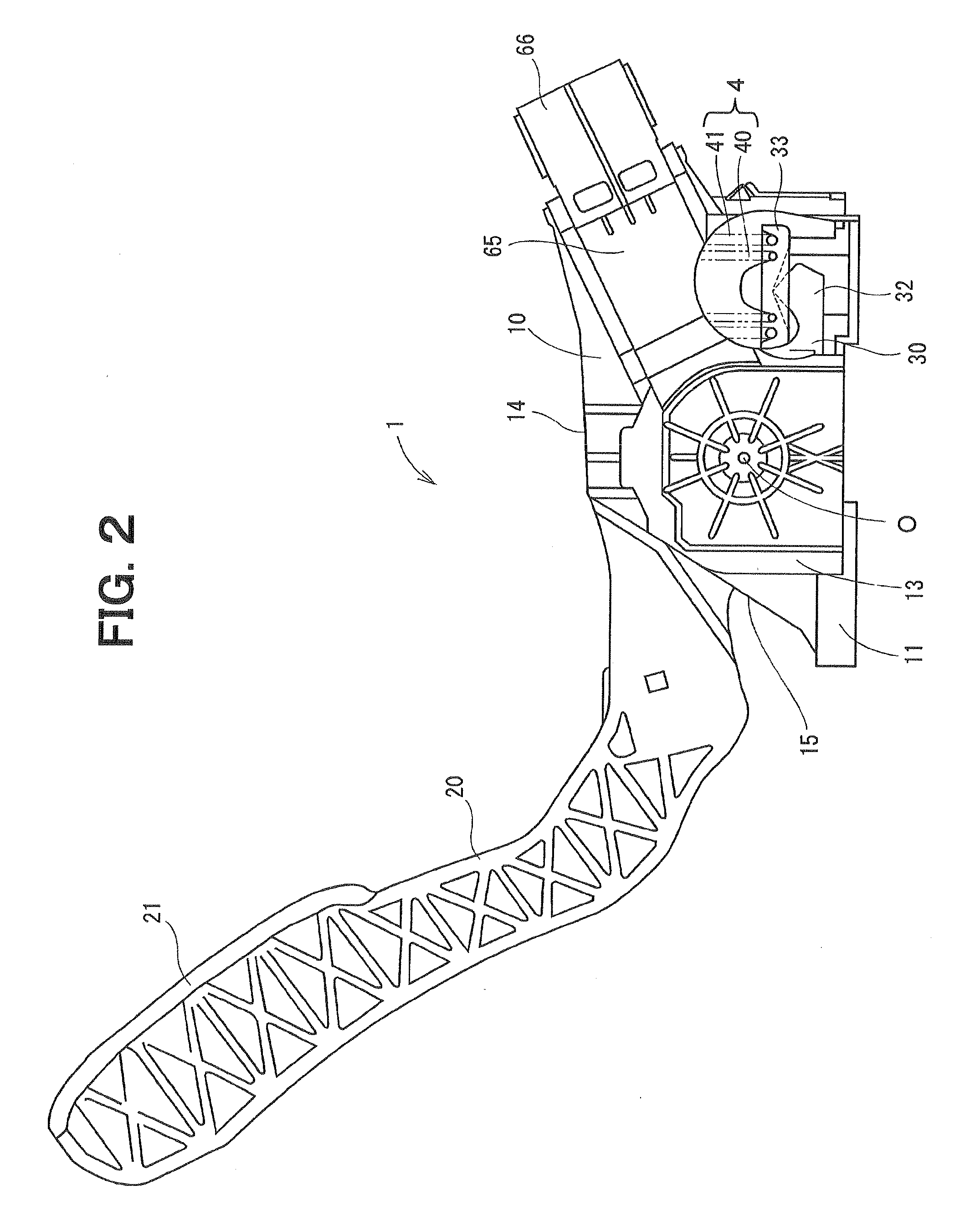
[0020]First of all, a structure of the accelerator pedal module will be described with reference to FIGS. 2 and 3. The accelerator pedal module 1 includes a housing 10, the accelerator pedal 20, a pedal rotor 30, a double coil spring 4, a friction washer 50 and the rotational angle sensing device 60.
[0021]The housing 10 includes a bottom plate 11, side plates 12, 13 and a top plate 14, which are formed integrally. The bottom plate 11 is installable to a vehicle body. The...
second embodiment
[0045]FIG. 5 shows a rotational angle sensing device 80 according to a second embodiment of the present invention. In the present embodiment, yokes (more specifically, yoke segments of a yoke configured into the tubular form) 81, 82 are constructed from two plates (plate materials) made of the magnetic material.
[0046]The top yoke (top yoke segment of the yoke) 81 includes a top wall 811, a first right wall 812 and a first left wall 813. The top wall 811 is placed at the top side in the Y-direction. The first right wall 812 is placed at the right side in the X-direction. The first left wall 813 is placed at the left side in the X-direction.
[0047]The bottom yoke (bottom yoke segment of the yoke) 82 includes a bottom wall 821, a second right wall 822 and a second left wall 823. The bottom wall 821 is placed at the bottom side in the Y-direction. The second right wall 822 is placed at the right side in the X-direction. The second left wall 823 is placed at the left side in the X-directi...
third embodiment
[0051]FIG. 6 shows a rotational angle sensing device 90 according to a third embodiment of the present invention. In the present embodiment, a yoke 91 is constructed from a single plate (plate material) made of the magnetic material.
[0052]The yoke 91 has a top wall 911, a bottom wall 912, a right wall 913 and first and second left walls 914, 915. The top wall 911 is placed at the top side in the Y-direction. The bottom wall 912 is placed at the bottom side in the Y-direction. The right wall 913 is placed at the right side in the X-direction. The first and second left walls 914, 915 are placed at the left side in the X-direction. A circumferential end part of the first left wall 914 and a circumferential end part of the second left wall 915 contact with each other and form a contact portion 916. The contact portion 916 is placed outward of the first magnet 61 in the radial direction of the yoke 91.
[0053]As indicated by an arrow φ11, the magnetic flux flows through the magnetic circui...
PUM
 Abstract
Description
Claims
Application Information