Data Transmission Control Methods And Devices

a data transmission and control method technology, applied in data switching networks, frequency-division multiplexes, instruments, etc., to achieve the effect of improving control

Active Publication Date: 2011-04-07
TELEFON AB LM ERICSSON (PUBL)
View PDF14 Cites 4 Cited by
  • Summary
  • Abstract
  • Description
  • Claims
  • Application Information

AI Technical Summary

Benefits of technology

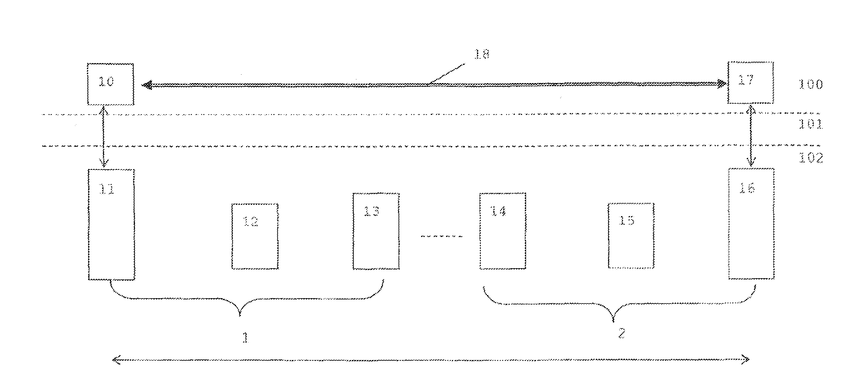
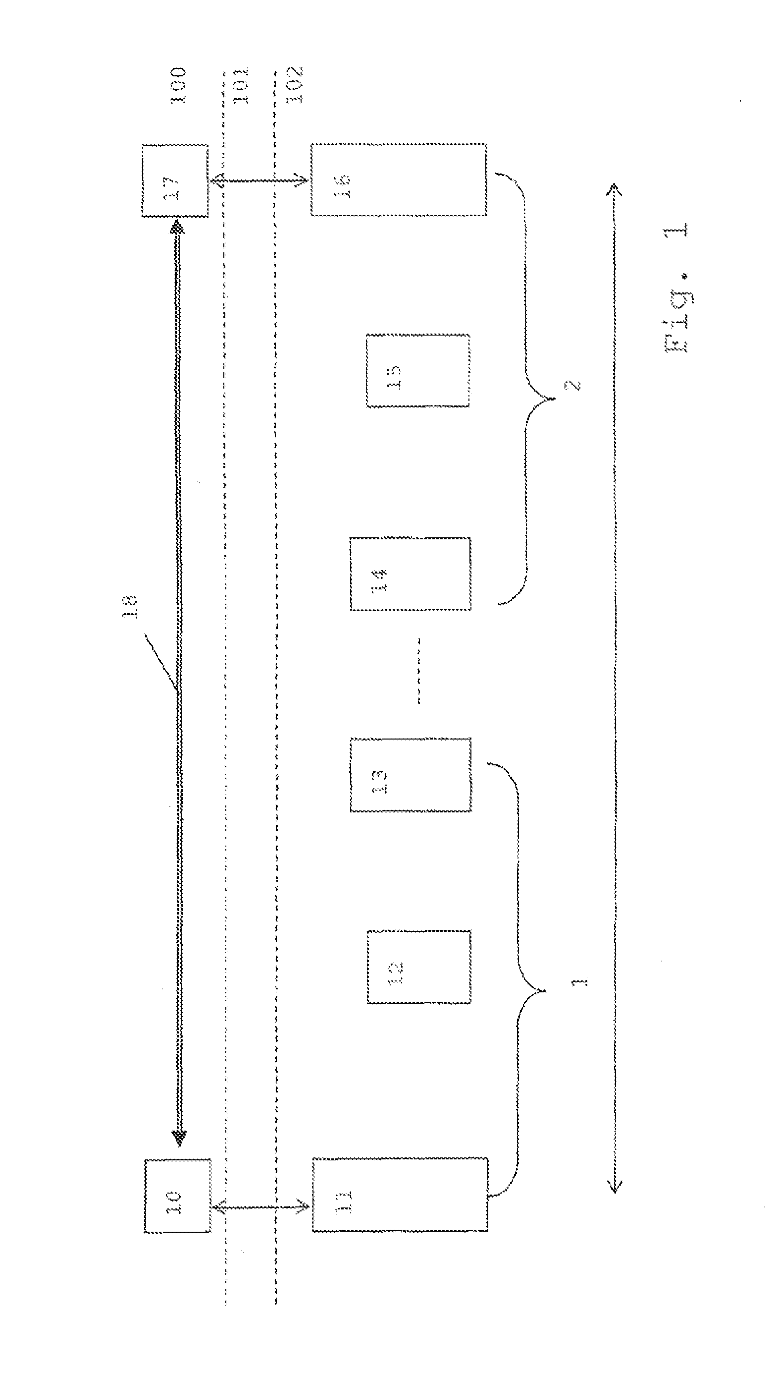
[0011]According to embodiments of the present invention, a control operation on the part of the network for influencing the data rate of a data source is done with the help of setting a congestion indication marking in data units being sent from a data source to a receiver. The receiver then sends an appropriate control message to the data source. Such a congestion indication marking can e.g. be an Explicit Congestion Notification in an IP header of said data units. Using congestion indication markings has the advantage of simplicity over procedures for directly signalling from a network entity to a data source. Especially, the network entities performing the control operation do not need to have any knowledge of the specifics of the data source and its rate adaptation mechanism. Rather, the actual rate adaptation is done at the application layer at which the data source and receiver reside, and the network entities at lower layers only provide input in the form of a generic congestion indication. In this way the rate reduction scheme at the communication end points is agnostic to the underlying network technology, which makes it applicable to all kinds of different network technologies (both 3GPP access systems and non-3GPP access systems), while the scheme for adding congestion indication markings at the access network level can be agnostic to the specifics of the rate adaptivity in the data source, i.e. requires no knowledge of the source codecs or of the transport layer specifics, and can therefore be used with either real-time transport protocols like UDP (User Datagram Protocol) or reliable transport protocols like TCP (Transmission Control Protocol). In summary this leads to a very flexible but at the same time also simple system for letting the network influence the sending rate of a data source.
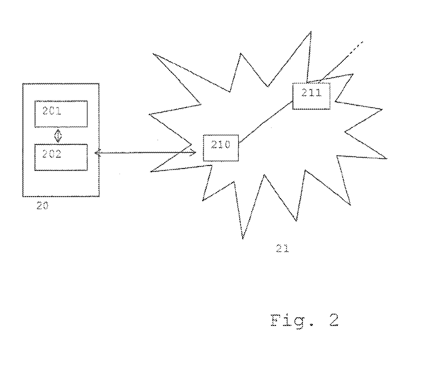
[0015]In this aspect, a radio access network entity marks data units based on the radio communication quality between the terminal and the radio access point, e.g. a base station. The radio access network entity performing the marking may be located at the radio access point or further on the network communication path. The quality can be determined based on one or more of e.g. the signal strength, on the bit error rate or on dedicated quality indicators such as Channel Quality Indicators (CQI). The quality can be determined in the uplink or downlink direction, where it is preferable that at least the uplink quality is observed. As a consequence, the radio access entity can operate to reduce the sending rate of the data source with a simple feedback mechanism (congestion indication marking) if it determines that the radio communication quality has been degraded below a given level, such that the data source does not experience an uncontrolled loss of transmission quality if it sends at a rate that the radio link can not or soon will not be able to support. It is noted that the radio communication degradation condition can be chosen in such a way that it reflects a quality level before communication problems occur, in order to warn of an upcoming problem.
[0019]In this aspect, if the receiver of the communication detects the presence of feedback from the network that indicates that the data source should reduce its rate, namely the presence of the congestion indication marking, it instructs the data source to reduce its rate and at the same time gives an upper bound value that depends on the minimum transmission capacity associated with the transport service provided to the receiver. For example, if the minimum transmission capacity is a guaranteed bit rate, then the receiver can indicate to the data source that its sending bit rate should not exceed the value of the guaranteed bit rate associated with the transport service offered to the terminal associated with the receiver. In this way, improved control can be achieved, as the data source not only receives an indication to reduce its sending rate, but furthermore obtains dedicated knowledge of an upper bound.

Problems solved by technology

In such systems, there exists the basic problem of providing the network with a means for controlling the data rate of the rate adaptive source.

Method used


Image

  • Data Transmission Control Methods And Devices
  • Data Transmission Control Methods And Devices
  • Data Transmission Control Methods And Devices

Examples


Embodiment Construction

[0037]In the following, detailed examples of the invention will be described. It is noted that reference will be made to specific technologies and standards, such as GPRS (General Packet Radio Service) or 3GPP TS23.401, but such references only serve to indicate preferred examples and are in no way limiting. Rather, the present invention can be generally applied in the context of any communication system that provides for the use of specified transport services (such as bearers) that are characterised by at least a parameter indicating a minimum transmission capacity and where a data source associated with a terminal can adjust its transmission rate. However, it is noted that EPS systems are a preferred application of the invention.

[0038]A transport service within the meaning of the present specification and claims is a service offered to a terminal for transporting data units. The transport service is characterized by a set of values associated with respective service quality param...


PUM


Abstract

A method of controlling a radio access network entity of a data unit communication network is described, said radio access network entity being involved in providing a transport service to a radio terminal of said data unit communication network, said transport service being characterized by a set of values associated with respective service quality parameters, said method comprising: monitoring (S30) a communication quality at the radio access level of a communication between said terminal and an access point of said radio access network, and setting (S31) a congestion indication marking in data units of said transport service if said communication quality fulfils a radio communication degradation condition.

Description

[0001]This application is a continuation application which claims the benefit of pending patent application Ser. No. 12 / 678,208 filed on Jun. 2, 2010 which was an application under 35 U.S.C. 371 of PCT / EP08 / 60939 filed on Aug. 21, 2008, which claims priority from EP 07016492.6 filed on Aug. 22, 2007 and EP 07118035.0 filed on Oct. 8, 2007, the disclosures of which are fully incorporated herein by reference.BACKGROUND OF THE INVENTION[0002]The present invention relates to methods and devices for controlling a data transmission over a data unit communication network using a specified transport service offered by the data unit communication network to a terminal.BACKGROUND[0003]In the field of data unit communications it is known to offer a specified transport service for the transmission of data units over a network. Such a transport service is constituted by associating certain values with service quality parameters of the transport service, e.g. assigning a value to a minimum transm...

Claims


Application Information

Patent Timeline
Patent Type & Authority Applications(United States)
IPC IPC(8): H04L12/26H04L47/31
CPCH04L47/31H04W72/1205H04W28/02H04L47/14H04L47/10H04W28/22H04W8/04H04W72/12H04W28/0252H04W28/0268H04W28/10H04L1/0002H04L47/11H04L47/12H04L47/24
Inventor LUDWIG, REINERENSTROM, DANIELJOHANSSON, INGEMARHEDBERG, TOMAS
Owner TELEFON AB LM ERICSSON (PUBL)
Why Eureka
Try Eureka