Driving-force transmitting apparatus for four-wheel-drive vehicle

a technology of driving force and transmitting apparatus, which is applied in mechanical equipment, transportation and packaging, gearing, etc., can solve the problems of disadvantageous degradation of fuel efficiency even in two-wheel drive mode, and achieve the effect of reducing fuel efficiency in two-wheel driv

Inactive Publication Date: 2011-04-07
UNIVANCE CORP
View PDF6 Cites 29 Cited by
  • Summary
  • Abstract
  • Description
  • Claims
  • Application Information

AI Technical Summary

Benefits of technology

[0010]According to the present invention, a driving-force transmitting apparatus for a four-wheel-drive vehicle is provided for achieving a reduction in fuel efficiency in t

Problems solved by technology

For this reason, in these conventional four-wheel-drive vehicles 612 and 712, fuel efficiency is disadvantageously deteriorated even in the two-wheel drive mode, compared with

Method used


Image

  • Driving-force transmitting apparatus for four-wheel-drive vehicle
  • Driving-force transmitting apparatus for four-wheel-drive vehicle
  • Driving-force transmitting apparatus for four-wheel-drive vehicle

Examples


second embodiment

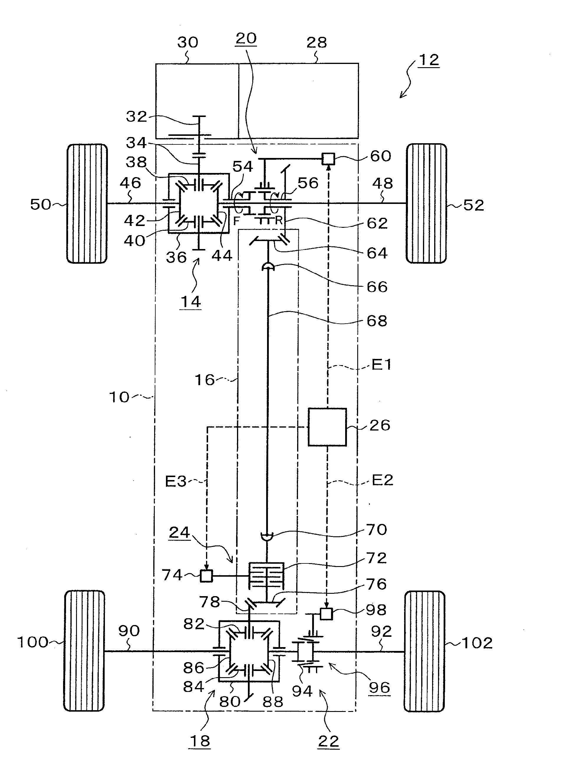
[0053]FIG. 8 is an illustrative diagram depicting the driving-force transmitting apparatus for a four-wheel-drive vehicle according to the present invention;

[0054]FIG. 9 is a section view depicting an embodiment of a rear-wheel differential device and a second disengaging mechanism of FIG. 8;

[0055]FIGS. 10A and 10B are illustrative diagrams depicting disconnectable conditions of the first disengaging mechanisms of FIG. 3 and FIG. 8;

[0056]FIGS. 11A, 11B, and 11C are illustrative diagrams depicting other embodiments of the second disengaging mechanisms of FIG. 3 and FIG. 8;

third embodiment

[0057]FIG. 12 is an illustrative diagram depicting the driving-force transmitting apparatus for a four-wheel-drive vehicle according to the present invention;

[0058]FIGS. 13A and 13B are illustrative diagrams depicting disengageable conditions of a first disengaging mechanism of FIG. 12;

fourth embodiment

[0059]FIG. 14 is an illustrative diagram depicting the driving-force transmitting apparatus for a four-wheel-drive vehicle according to the present invention; and

[0060]FIGS. 15A and 15B are illustrative diagrams depicting disengageable conditions of a first disengaging mechanism of FIG. 14.

DETAILED DESCRIPTION OF THE PREFERRED EMBODIMENT

[0061]The driving-force transmitting apparatus for a four-wheel-drive vehicle of the present invention is described in detail below based on the drawings that depict embodiments. Each embodiment depicts an FF (Front-engine Front-drive)-vehicle-base four-wheel-drive vehicle that drives front wheels in two-wheel drive or a FR (Front-engine Rear-drive)-vehicle-base four-wheel-drive vehicle that drives rear wheels in two-wheel drive. Also, in the four-wheel-drive vehicle of each embodiment, at least an engine and a driving-force transmitting apparatus are controlled by an ECU (Electronic Control Unit) based on detection value of various vehicle-state det...


PUM


Abstract

A driving-force transmitting device includes a first disengaging mechanism that disengages a driving force from an engine to a driving-force transmitting unit and a second disengaging mechanism having a synchronizing mechanism that disengages the driving force from a driving-force transmitting unit to a right-rear-wheel driving shaft. A change gear ratio between front wheels and rear wheels is constructed so that a driving-force transmitting unit side of the first disengaging mechanism rotates at a speed higher than that of an opposing side at the time of completion of synchronization of the second disengaging mechanism. In switching from a two-wheel drive mode to a four-wheel drive mode, synchronization of the second disengaging mechanism first starts to increase the rotation speed of the driving-force transmitting unit, and next connects the first disengaging mechanism when a rotation speed of the driving-force transmitting unit side of the first disengaging mechanism matches that of an opposing side.

Description

[0001]This application is a priority based on prior application No. JP 2009-104752, filed Oct. 10, 2009 in Japan.BACKGROUND OF THE INVENTION[0002]1. Field of the Invention[0003]The present invention relates to driving-force transmitting apparatuses for four-wheel-drive vehicles capable of switching between two-wheel drive and four-wheel drive and, in particular, a driving-force transmitting apparatus for a four-wheel-drive vehicle stopping the rotation of a portion not related to transmission of driving force in two-wheel drive.[0004]2. Description of the Related Arts[0005]In a conventional so-called on-demand-type full-time four-wheel-drive vehicle, as an example of a driving-force transmitting apparatus for an FF-vehicle-base four-wheel-drive vehicle that uses an electronic control coupling device to control distribution of a driving force in a manner such that front wheels are driven in a two-wheel-drive mode and rear wheels are driven in a four-wheel-drive mode, an apparatus sho...

Claims


Application Information

Patent Timeline
IPC IPC(8): F16H3/44
CPCB60K17/344Y02T10/52B60K23/08B60K17/348Y02T10/40
Inventor KATO, TADAHIKOMIYACHI, TOSHIYUKI
Owner UNIVANCE CORP
Why Eureka
Try Eureka