Device for loading particles of catatlyst into tubes having an annular zone

Inactive Publication Date: 2011-04-14
INST FR DU PETROLE
View PDF28 Cites 21 Cited by
  • Summary
  • Abstract
  • Description
  • Claims
  • Application Information

AI Technical Summary

Benefits of technology

[0039]Said centralizers are distributed along the bayonet tube and also contribute

Problems solved by technology

That method results in dense, homogeneous loading but requires equipment for causing rotation that can distribute the catalyst over several radii in order to cover all of the catalytic section properly.
The prior a

Method used


Image

  • Device for loading particles of catatlyst into tubes having an annular zone
  • Device for loading particles of catatlyst into tubes having an annular zone
  • Device for loading particles of catatlyst into tubes having an annular zone

Examples


Embodiment Construction

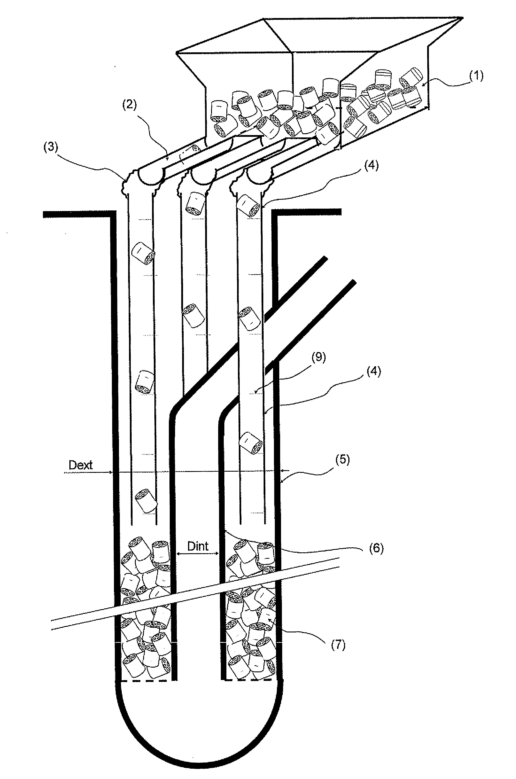
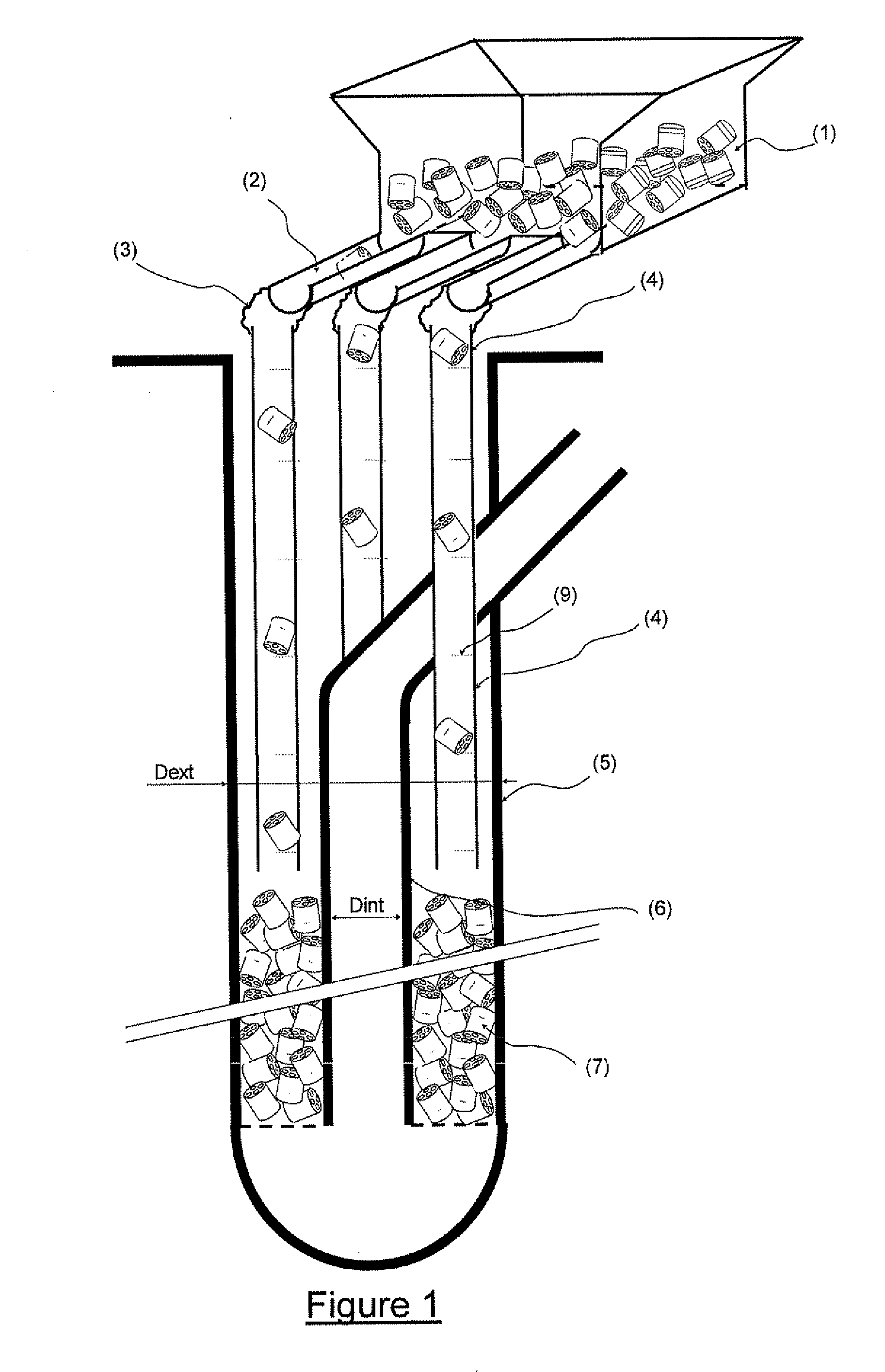
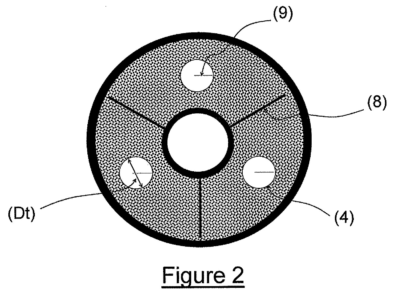
[0052]The device for loading particles of catalyst into the annular zone of a bayonet tube comprises the following elements which are described in the order in which the catalyst particles advance. The numbers refer to FIGS. 1 and 2:[0053]a loading hopper (1), which may be of any type known to the skilled person;[0054]a set of N vibrating chutes (2) one end of which penetrates into the lower zone of the loading hopper (1), with the other end being in communication with each loading tube (4) via flexible connection elements (3);[0055]a set of N loading tubes (4) penetrating into each angular sector, the diameter Dt of one loading tube satisfying two conditions, a) more than 1.1 times the largest dimension, dmax, of the particles to be loaded, and b) less than 2 times the smallest dimension, dmin, of the particles to be loaded.

[0056]This set may be completed by a system for extracting fine particles of catalyst (10, 12 in FIG. 3).

[0057]In order to slow down the fall of particles of ca...


PUM

PropertyMeasurementUnit
Lengthaaaaaaaaaa
Lengthaaaaaaaaaa
Heightaaaaaaaaaa

Abstract

A device and method to load particles of catalyst on the order of cm in the principal dimension into an annular zone of reaction tubes which may reach a height of more than 10 metres, while satisfying the strict conditions of homogeneity and density of loading.

Description


Claims


Application Information

Patent Timeline
Owner INST FR DU PETROLE
Why Eureka
Try Eureka