Railroad crossing

a railroad crossing and railroad technology, applied in the direction of traffic crossing safety means, transportation and packaging, instruments, etc., can solve the problems of high risk of rail operators, pedestrians and road users, and many car/train accidents, and achieve low cost, effective railroad crossing, and improved safety

Inactive Publication Date: 2011-04-14
STI GLOBAL LTD
View PDF1 Cites 49 Cited by
  • Summary
  • Abstract
  • Description
  • Claims
  • Application Information

AI Technical Summary

Benefits of technology

[0068]In a further preferred arrangement the railroad crossing protection system further includes an in-vehicle system to further aid the decision process at the railroad crossing.
[0070]The present invention provides a low-cost, effective railroad crossing solution by providing an identification and warning to drivers approaching any passive railroad crossing in a network, and secondly, the ability to monitor all road traffic behaviour at a crossing. The system offers an integrated solution for, or substitution of, existing signalling methods for risk minimisation, train tracking and track performance, and accident prevention at both passive and active road and railroad crossings. The present invention also provides for video capture of every ‘incident’ and web-based flexibility which includes up-to-date reporting. The video capture of any incident that occurs can be deployed alongside conventional crossing protection systems to improve safety, be used as an educational and law enforcement tool.

Problems solved by technology

But around the world, railroad crossings stilt represent a potential high risk for rail operators, pedestrians and road users.
Railroad crossings, intersections where a railroad track crosses a roadway, have long presented a significant danger for vehicular traffic.
Each year many car / train accidents occur at these locations.
A major drawback of conventional railroad crossing systems is the expense associated with installing and maintaining these systems.
Further, these arrangements provide only limited information to vehicle operators concerning the approaching train.
With the abovementioned safety measures in place, as well as the implementation of driver education programs, there are still too many accidents occurring at railroad crossings.
These accidents extract a high toll in injury and death, and impose a large economic cost on the community.
Or they are impatient, and attempt to drive through the crossing or around the boom gates.
Not only are they breaking the law—these actions often end in tragedy.

Method used


Image

  • Railroad crossing
  • Railroad crossing
  • Railroad crossing

Examples


Embodiment Construction

[0081]The present invention will be discussed hereinafter in detail in terms of the preferred embodiment of a system and method of an improved railroad crossing according to the present invention with reference to the accompanying drawings. In the following description, numerous specific details are set forth in order to provide a thorough understanding of the present invention. It will be obvious, however, to those skilled in the art that the present invention may be practiced without these specific details.

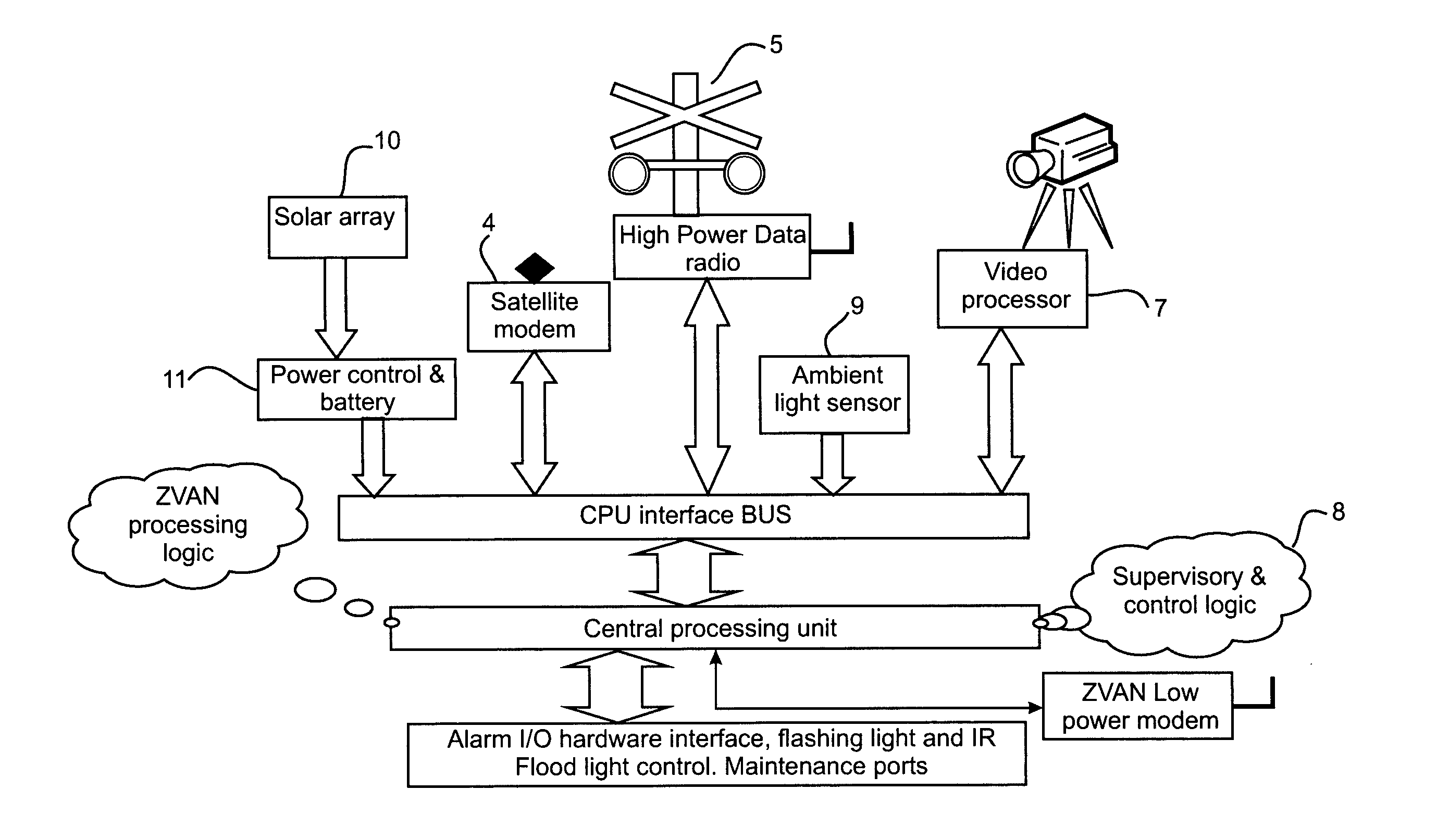
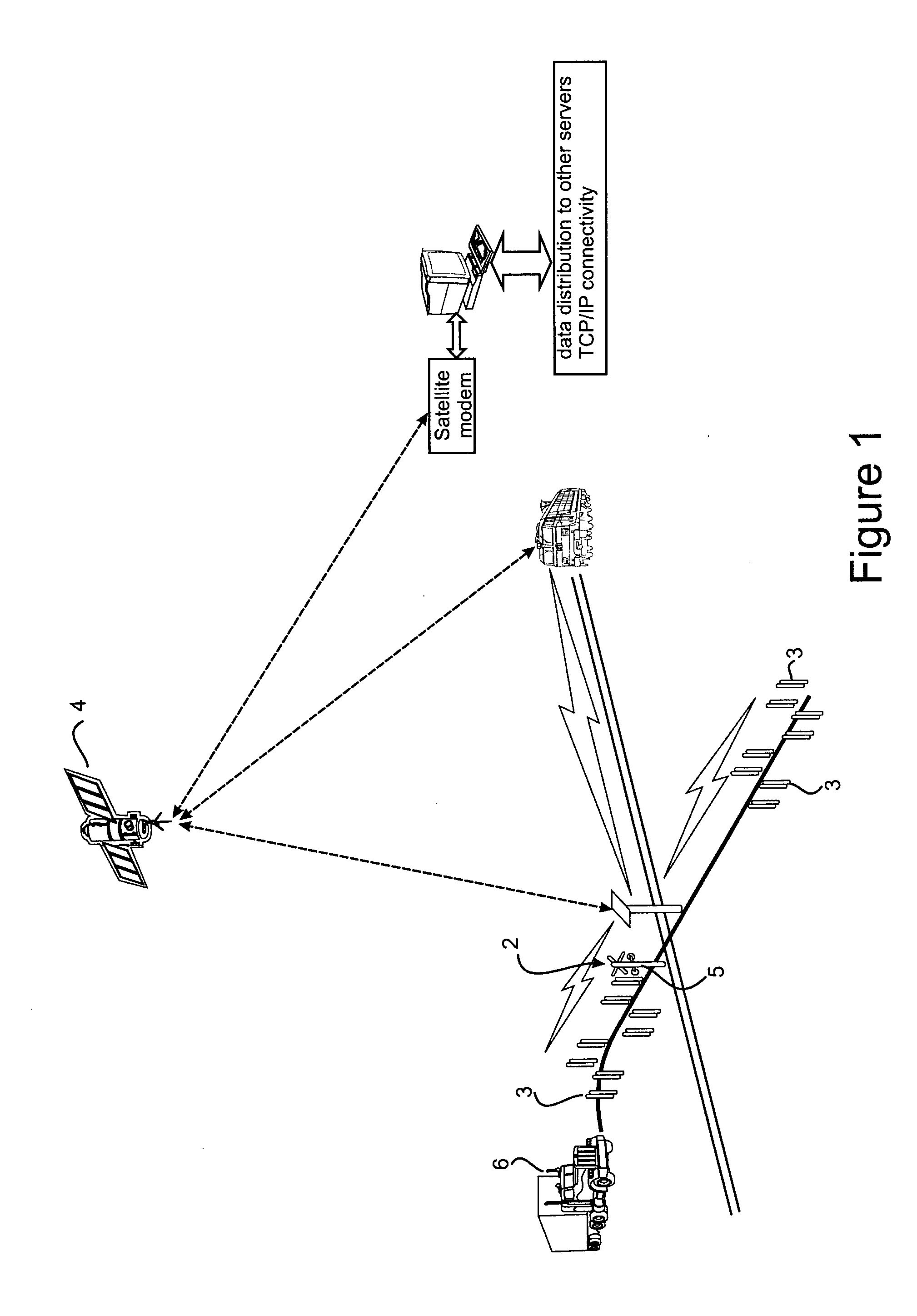
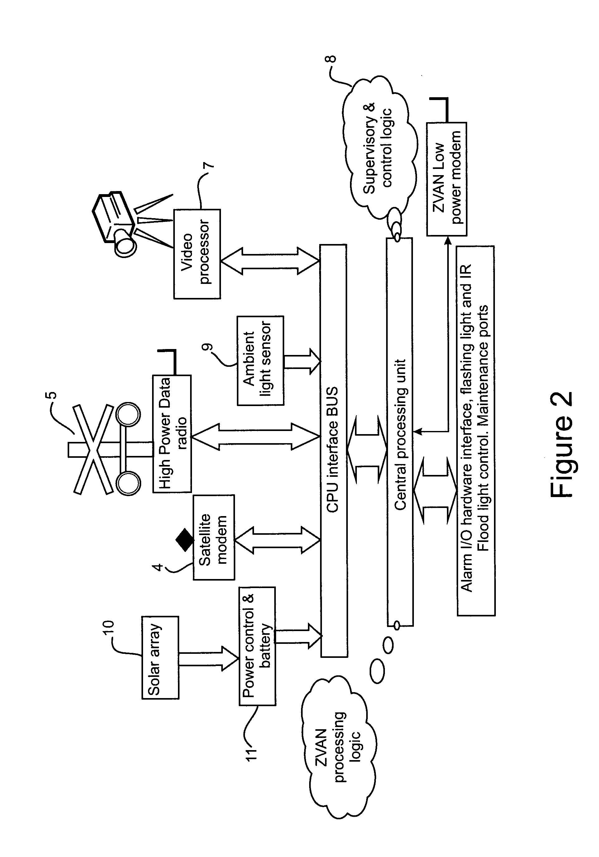
[0082]The improved railroad crossing ideally involves two elements: a train integrity network system (TINS), located in the locomotive and as incorporated by reference from the applicant's international application number PCT / AU2005 / 000624 and a trackside crossing protection technology (XPT) transponder which is located at each grade crossing.

[0083]The TINS server is installed in the locomotive and incorporates the XPT software suite, a GPS module, an RF modem, and a database of...


PUM


Abstract

A method of operating a railway crossing including the steps of receiving a signal from a locomotive; and activating crossing warning devices and / or downroad warning and in-vehicle alert devices.

Description

FIELD OF THE INVENTION[0001]The invention relates generally to railroad crossing systems. In particular, the invention relates to the indication and capture of crossing conditions.BACKGROUND TO THE INVENTION[0002]The movement of passengers and freight is vital and in most industrialised economies it is one of the safest growing modes of transport. But around the world, railroad crossings stilt represent a potential high risk for rail operators, pedestrians and road users. Railroad crossings, intersections where a railroad track crosses a roadway, have long presented a significant danger for vehicular traffic. Each year many car / train accidents occur at these locations.[0003]Extensive measures have been adopted at railroad crossings to provide a safer environment for all users. This has included flashing lights, vehicle and pedestrian boom gates and other warnings systems to notify motorists and pedestrians of the presence of trains near or approaching the railroad crossing. The pres...

Claims


Application Information

Patent Timeline
Patent Type & Authority Applications(United States)
IPC IPC(8): B61L29/30G01B11/14G01P15/00
CPCB61L23/041B61L29/246B61L29/32B61L29/30B61L29/28
Inventor REICHELT, KEVIN ALLANSEARLE, DONALD STEPHEN
Owner STI GLOBAL LTD
Why Eureka
Try Eureka