Resistance Measurement in High Power Apparatus Environments

Active Publication Date: 2011-04-14
MEGGER SWEDEN
View PDF4 Cites 21 Cited by
  • Summary
  • Abstract
  • Description
  • Claims
  • Application Information

AI Technical Summary

Benefits of technology

[0006]An object of the present invention is to provide a measuring device for high voltage apparatus environments, which is easy to use and provides for continuous operation.
[0009]By using a capacitor as current source, the weight of the measuring device is kept to a minimum, facilitating the use thereof.
[0012]In an alternative embodiment, the current source comprises two capacitors in bipolar connection. The usage of two capacitors in bipolar connection reduces the remanence of the inductors tested, such as current transformers. By alternating discharge of capacitors the remaining magnetization is decreased.

Problems solved by technology

Conventional prior art measuring devices are bulky and heavy due to the batteries or accumulators, often lead batteries, provided in the device for providing the high current required for accurate measurement.

Method used


Image

  • Resistance Measurement in High Power Apparatus Environments
  • Resistance Measurement in High Power Apparatus Environments
  • Resistance Measurement in High Power Apparatus Environments

Examples


Embodiment Construction

[0021]In the following, a detailed description of preferred embodiments of a measuring device according to the invention will be given.

[0022]In the following description and claims, the term high power is used. It is to be understood that this term is intended to cover voltages of at least 400 volts or at least 10 kilovolts and up to 1 Megavolts.

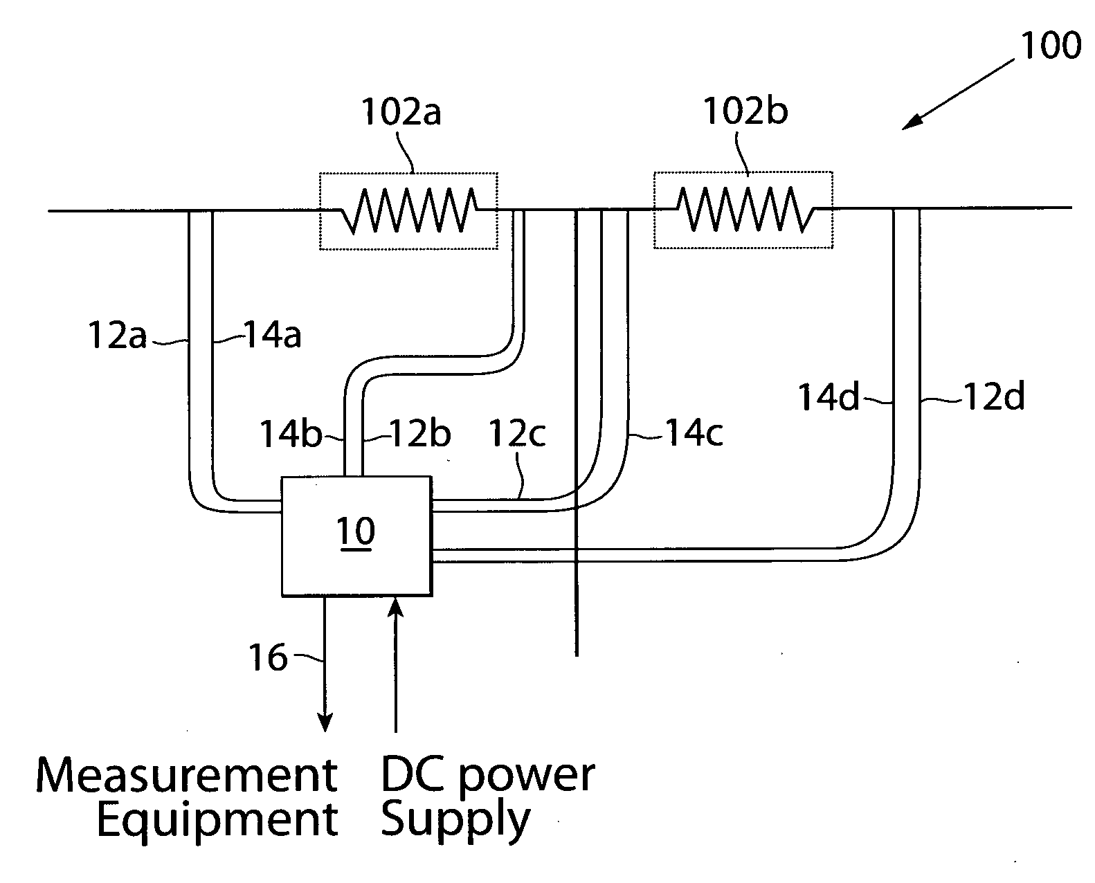
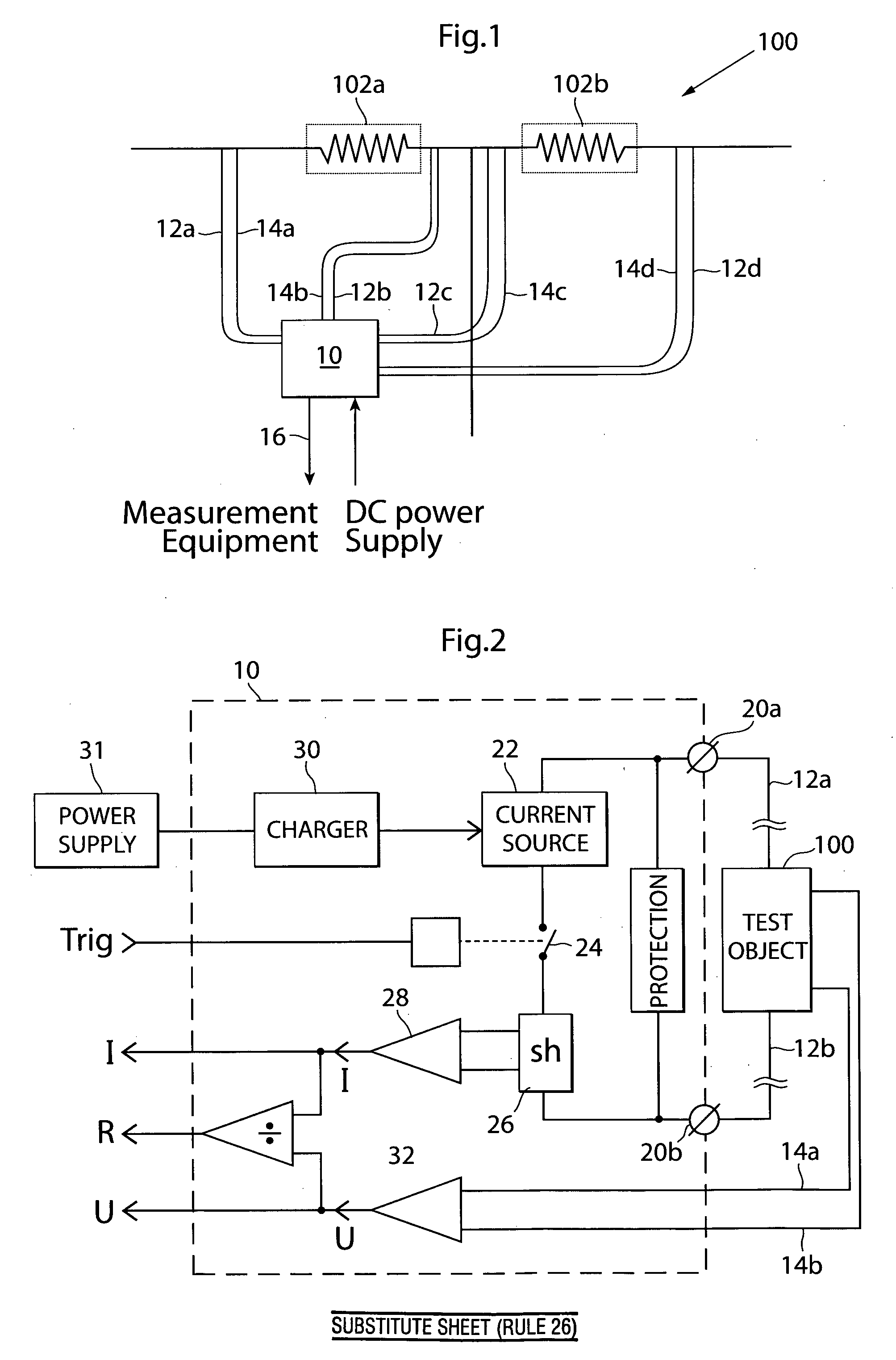
[0023]First with reference to FIG. 1, the general configuration of a measuring device is shown, in this case connected to a test object in the form of a circuit breaker for measuring the internal resistance of this circuit breaker. The measuring device, generally designated 10, is connected to the circuit breaker, designated 100, by means of two pairs of current injection cables 12a, 12b and 12c, 12d, respectively. Each pair of current injection cables is connected on either side of an insulator 102a, 102b of the circuit breaker 100. Each insulator comprises or houses a breaking device for interrupting current flowing through the circuit bre...


PUM


Abstract

A measuring device for measuring the resistance of high power apparatuses comprises a current source connect-able to a test object, and means for measuring, wherein the current source is a capacitor. By providing the current source as a capacitor, a light weight device is obtained which can be used essentially continuously without periods of non-use during recharging.

Description

FIELD OF INVENTION[0001]The present invention relates generally to a device for measuring resistance in high power apparatuses, such as circuit breakers, bus bars, ground grids and disconnector switches, and more particularly to a measuring device comprising a high capacitive capacitor for generating a high current through the measured object.BACKGROUND[0002]There is a need for measurement of resistance in the range of μΩ-mΩ of any high voltage environment object, such as circuit breakers, bus bars, contacts, joints, ground grids etc. based on temporary high current generation.[0003]One way of achieving such measurement is to generate and apply a high current, more than 100 Amperes and preferably more than 250 Amperes during a short time (a few seconds and preferably less than two seconds) to measure extremely low resistances from less than 1 μΩ to 20 mΩ as a static value (Static Resistance Measurement—SRM) or as a high frequency sampled time series (Dynamic Resistance Measurement—D...

Claims


Application Information

Patent Timeline
IPC IPC(8): G01R27/08
CPCG01R31/3274
Inventor STANISIC, ZORANWERNLI, HEINZDOUIB, ROMAINWACKLEN, NILS
Owner MEGGER SWEDEN
Why Eureka
Try Eureka