Apparatus for optical fiber testing

a technology of optical fiber and apparatus, applied in the field of apparatus for optical fiber testing, can solve the problems of time-consuming and laborious changes of connectors, equipment damage or impairment of connections, and operating conditions in a cramped environmen

Inactive Publication Date: 2011-04-14
VERIZON PATENT & LICENSING INC
View PDF3 Cites 21 Cited by
  • Summary
  • Abstract
  • Description
  • Claims
  • Application Information

AI Technical Summary

Problems solved by technology

Changing connectors requires time and risks damage to the equipment or impairment to the connection via exposure to contaminants.
Additionally, the operating conditions may be in a cramped environment, such as a manhole.
Connectors may frequently be lost or damaged.
The switching between multiple connectors and pieces of equipment requires time to avoid damage, contamination, loss, and mistakes.

Method used


Image

  • Apparatus for optical fiber testing
  • Apparatus for optical fiber testing
  • Apparatus for optical fiber testing

Examples


Embodiment Construction

[0017]Reference will now be made in detail to exemplary embodiments, examples of which are illustrated in the accompanying drawings. It should be appreciated that the same reference numbers will be used throughout the drawings to refer to the same or like parts. It should be appreciated that the following detailed description are exemplary and explanatory only and are not restrictive.

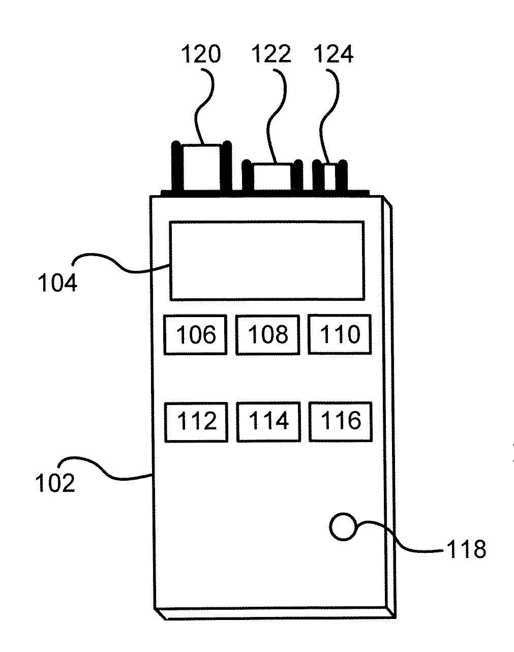
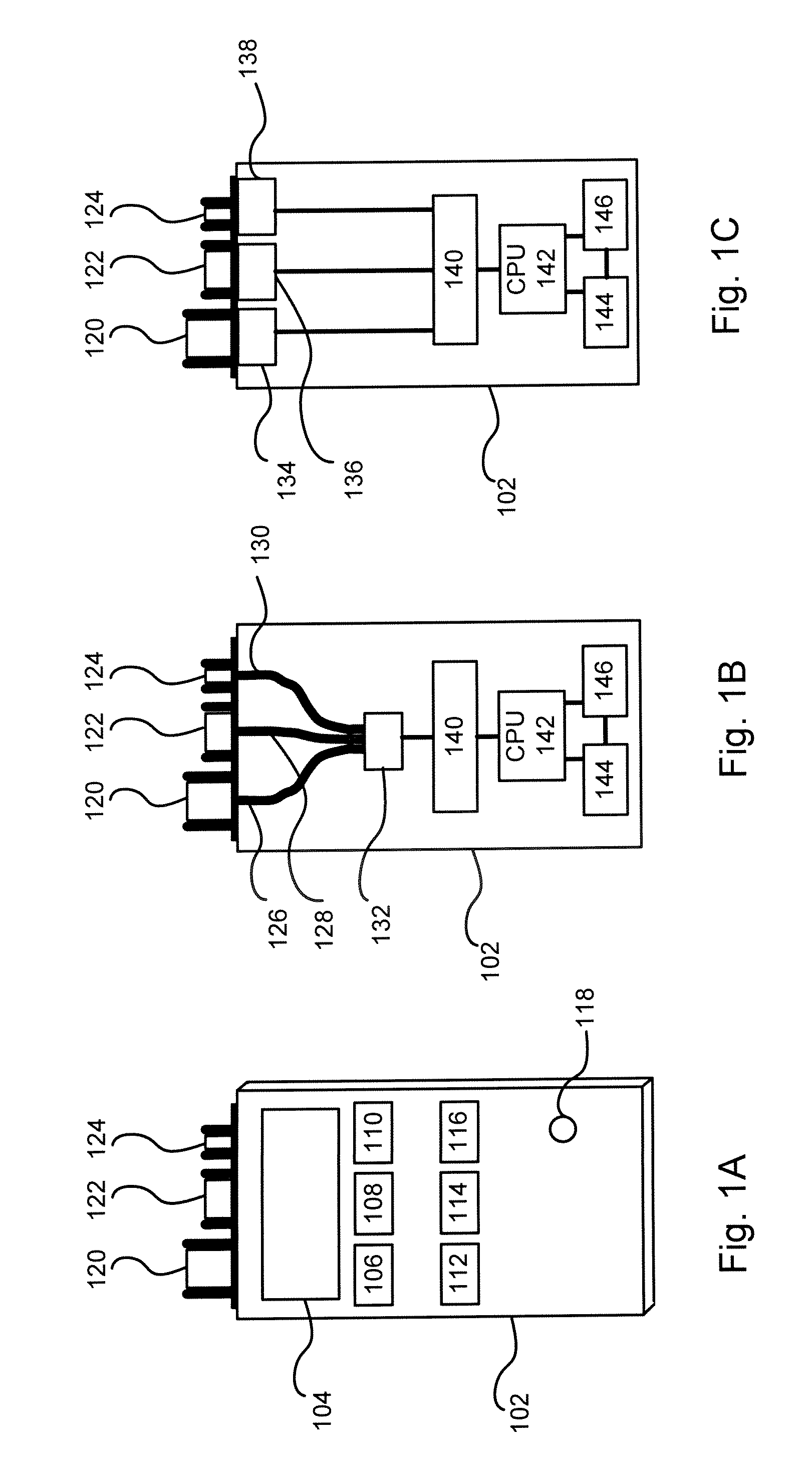
[0018]An exemplary embodiment provides a fiber optic diagnostic testing apparatus. The fiber optic diagnostic testing apparatus may provide a plurality of fiber optic connectors for transmitting and receiving signals. The plurality of connectors may allow coupling to fiber optic cables using connectors complying with a plurality of standards and interfaces.

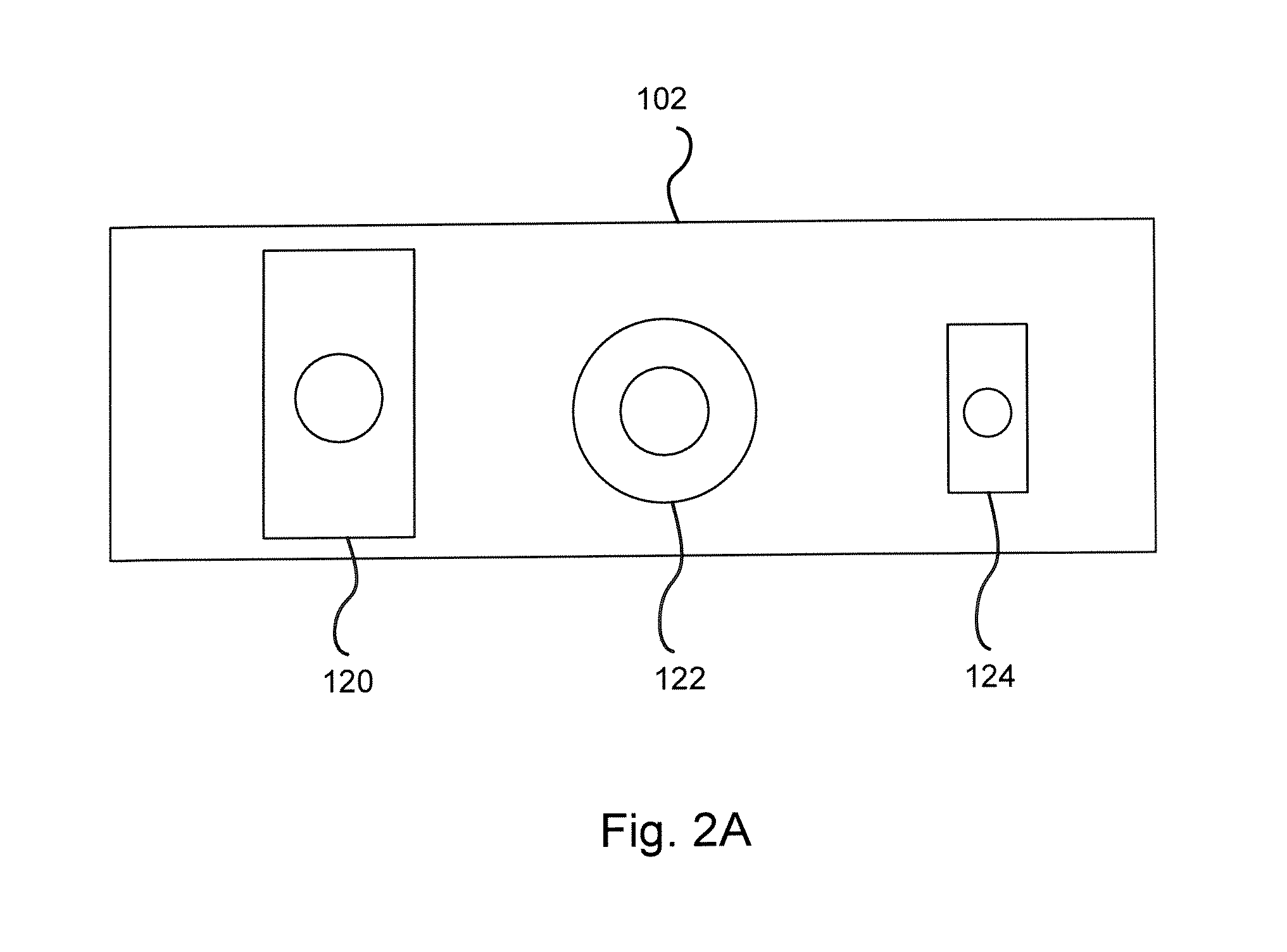
[0019]Referring to FIG. 1A, a fiber optic diagnostic testing apparatus in accordance with an exemplary embodiment is illustrated. Fiber optic diagnostic testing apparatus 102 may contain a plurality of fiber optic connectors for coupling to fiber opti...


PUM

PropertyMeasurementUnit
poweraaaaaaaaaa
wavelengthaaaaaaaaaa

Abstract

An apparatus for fiber optic testing is presented. In one exemplary embodiment, the apparatus may comprise a plurality of fiber optic connectors for coupling to one or more fiber optic cables, one or more photodetectors operatively connected to the plurality of fiber optic connectors, an optical power measurement module operatively connected to the one or more photodetectors, a display for displaying information received from the optical power measurement module, and one or more user controls for accepting user input.

Description

BACKGROUND INFORMATION [0001]Fiber optic diagnostic testing often occurs in the field. For example, fiber optic diagnostic testing is performed in central offices, at telecom sites, at carrier hotels, at enterprise network cabinets, at Controlled Environment Vaults (CEVs), in manholes, at handholes, or anywhere a fiber optic connector requires diagnosis. Diagnostic testing may be performed as part of system testing, trouble shooting, installation, and maintenance. Due to the variety of standards for fiber optic equipment, sale of telecom entities, evolution of fiber optic technology and other factors, a single fiber optic interface is not prevalent in the field. Telecom diagnostic equipment provides a single fiber optic interface. Changing fiber optic interfaces requires changing a connector on a piece of diagnostic equipment. Changing connectors requires time and risks damage to the equipment or impairment to the connection via exposure to contaminants. Additionally, the operating ...

Claims


Application Information

Patent Timeline
Patent Type & Authority Applications(United States)
IPC IPC(8): G01N21/84
CPCG01M11/3154G01M11/30
Inventor MOTTER, JEFFREY L.FASOLINO, JOHN A.FRANKS, STEVEN L.POLLOCK, MICHAEL D.CLARK, STEPHEN J.
Owner VERIZON PATENT & LICENSING INC
Why Eureka
Try Eureka