Aggregating ports while allowing access to singleton ports

a single-ton port and port aggregation technology, applied in the field of computer communication, can solve the problem that the end-point device cannot communicate with the additional device, and achieve the effect of small cos

Inactive Publication Date: 2011-04-14
GOOGLE TECH HLDG LLC
View PDF1 Cites 50 Cited by
  • Summary
  • Abstract
  • Description
  • Claims
  • Application Information

AI Technical Summary

Benefits of technology

[0007]Some embodiments assign routing costs to the aggregated port and to the singleton port. By assigning a s

Problems solved by technology

While these bridging architectures are able to use links based on multi-point technology, in practice they can only do so when the “multi-point” links are in fact restricted to supporting only two devices.
This restriction on the bridging architecture is so strong that if a logi

Method used


Image

  • Aggregating ports while allowing access to singleton ports
  • Aggregating ports while allowing access to singleton ports
  • Aggregating ports while allowing access to singleton ports

Examples


Embodiment Construction

[0015]Turning to the drawings, wherein like reference numerals refer to like elements, the invention is illustrated as being implemented in a suitable environment. The following description is based on embodiments of the invention and should not be taken as limiting the invention with regard to alternative embodiments that are not explicitly described herein.

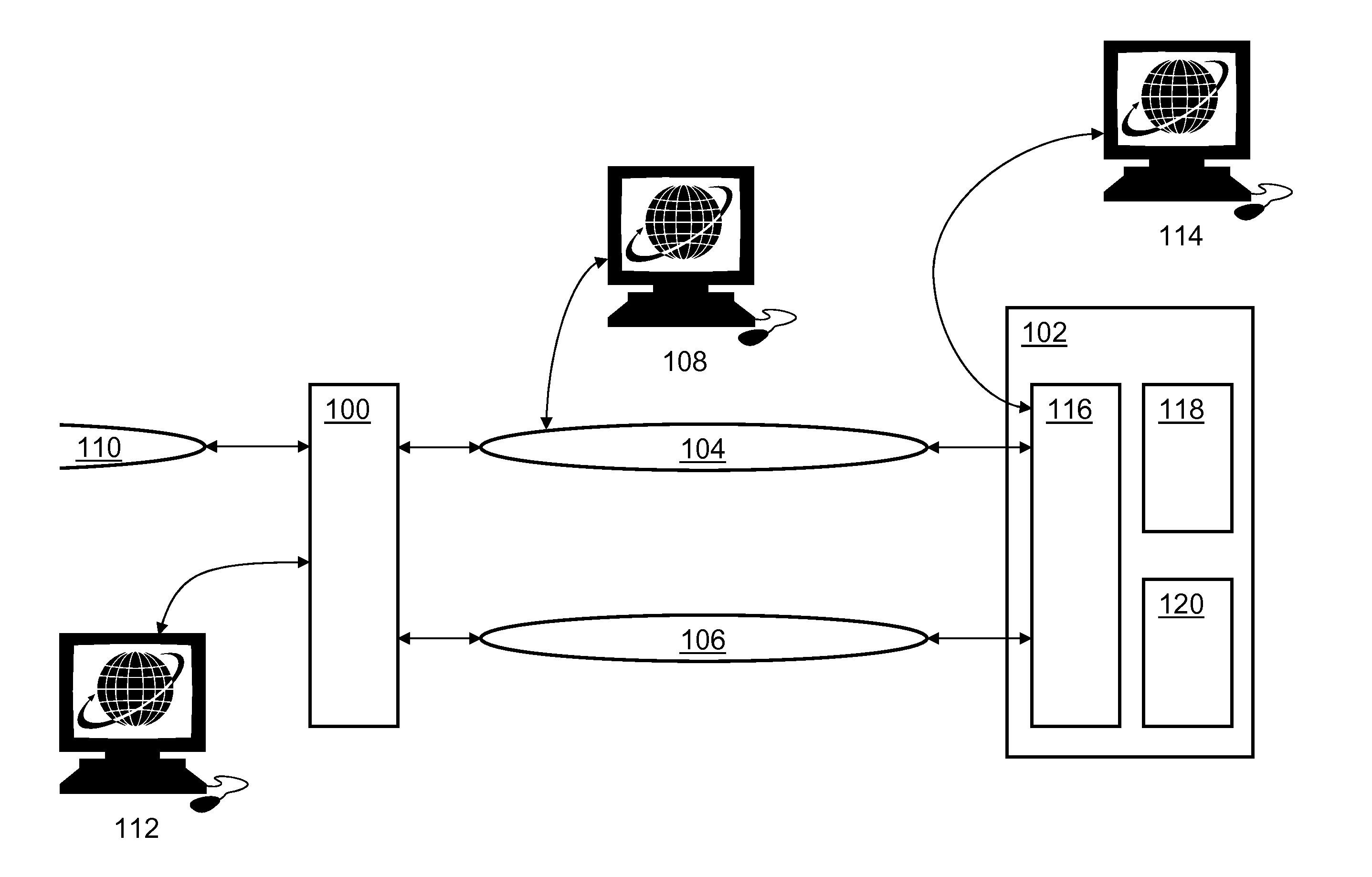
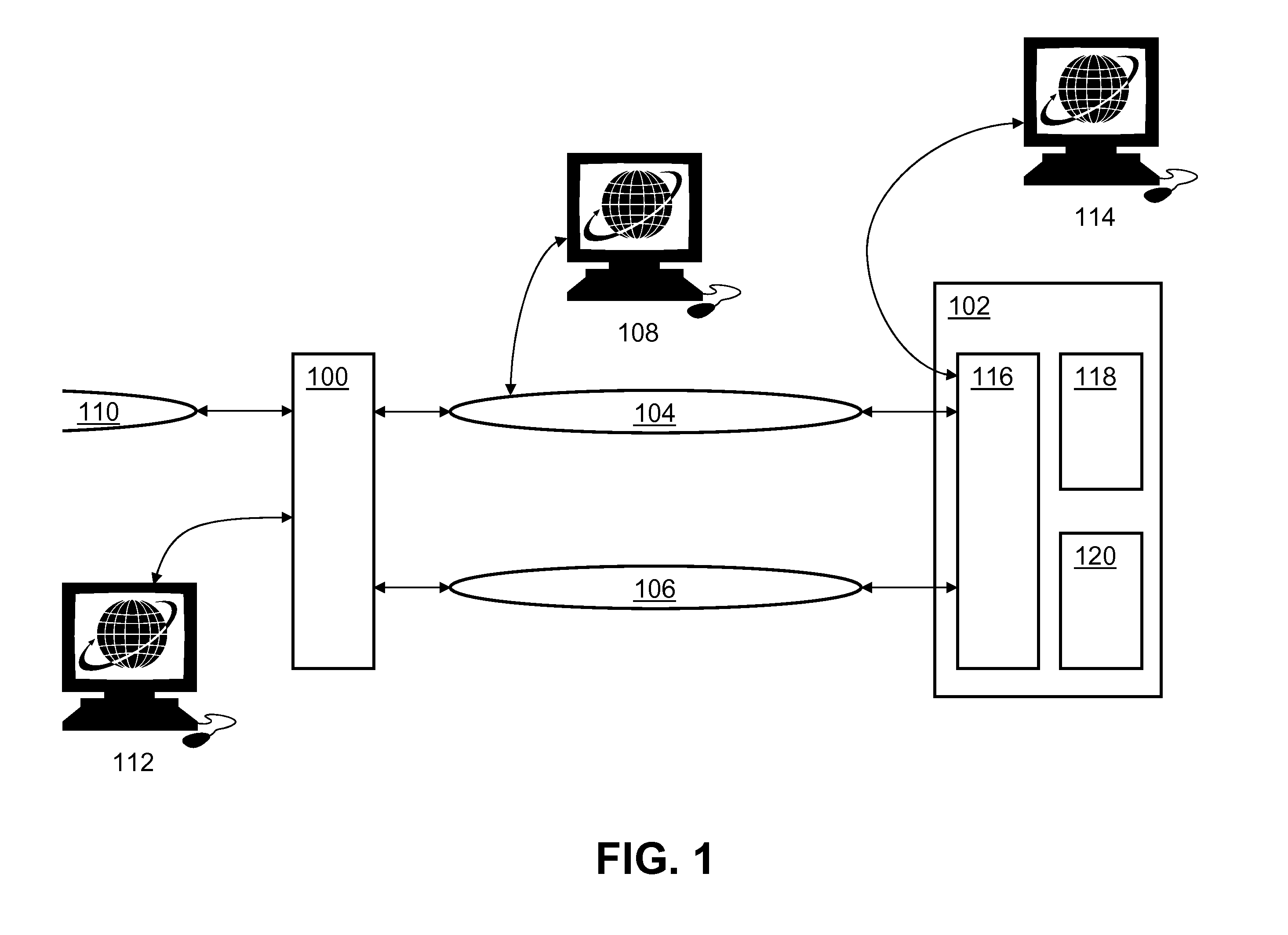
[0016]FIG. 1 shows a representative local communications environment. Two bridges 100, 102 are connected by at least two communications links 104, 106. The bridges 100, 102 of FIG. 1 are shown as stand-alone devices. In some situations, especially in homes or other small environments, there are no stand-alone bridge devices. Instead, bridging functions are performed by devices such as personal computers, networking hubs, or set-top boxes.

[0017]The communications links 104, 106 can represent any number of physical and logical technologies. They may be wired, optical, or wireless, for example. They do not need to be based on the s...


PUM


Abstract

Disclosed is a method for aggregating parallel data links connecting two end-point devices into a logical link. If one of the parallel data links is a multi-point link, then an end-point device can still access that link to route traffic to an end station on the link (that is, to a device other than the other end-point device of the logical data link). In the terminology of this disclosure, the logical aggregated link is accessed through an “aggregated port” on an end-point device, while the constituent multi-point link is accessed directly through a “singleton port.” By assigning a smaller cost to the aggregated port than to the singleton port, embodiments avoid creating routing loops. In some embodiments, the aggregation is performed at Layer 2 of the Open System Interconnection seven-layer protocol model. Then, the methods of the present invention work well with existing IEEE 802.1 bridging architectures and protocols.

Description

FIELD OF THE INVENTION[0001]The present invention is related generally to computer communications and, more particularly, to network bridging architectures.BACKGROUND OF THE INVENTION[0002]Computer networks have become standard features of many environments. Often, a new network is introduced alongside an existing network. The multiple networks may or may not share technologies (e.g., one can be wireless while another uses a coaxial cable), but they are often configured to share traffic. For example, a wireless device in a home seeking to access the Internet may direct its traffic to a wireless hub that connects to a DSL line for connectivity to an Internet service provider.[0003]Some network technologies provide “point-to-point” links, that is, links (usually wires or optical fibers) that connect one device to only one other device. Other network technologies (often based on coaxial cables or radio) are called “multi-point” and support many devices communicating simultaneously with...

Claims


Application Information

Patent Timeline
IPC IPC(8): H04L12/56H04L45/28H04L69/14
CPCH04L45/00H04L45/16Y02B60/33H04L45/48H04L45/245Y02D30/50H04L45/247H04L69/14H04L61/00H04L65/40
Inventor BAO, QIHARVEY, GEORGE A.JOHNSON, GERALD R.LEE, WHAY C.MICHAUD, TED R.
Owner GOOGLE TECH HLDG LLC
Why Eureka
Try Eureka