
Medium feeding device and recording apparatus

a feeding device and recording device technology, applied in the field of medium feeding, can solve the problems of bending of the guide path of the paper, disturbing the reverse feed, and affecting the quality of the paper

Active Publication Date: 2011-04-14
SEIKO EPSON CORP
View PDF3 Cites 8 Cited by
  • Summary
  • Abstract
  • Description
  • Claims
  • Application Information

AI Technical Summary

Benefits of technology

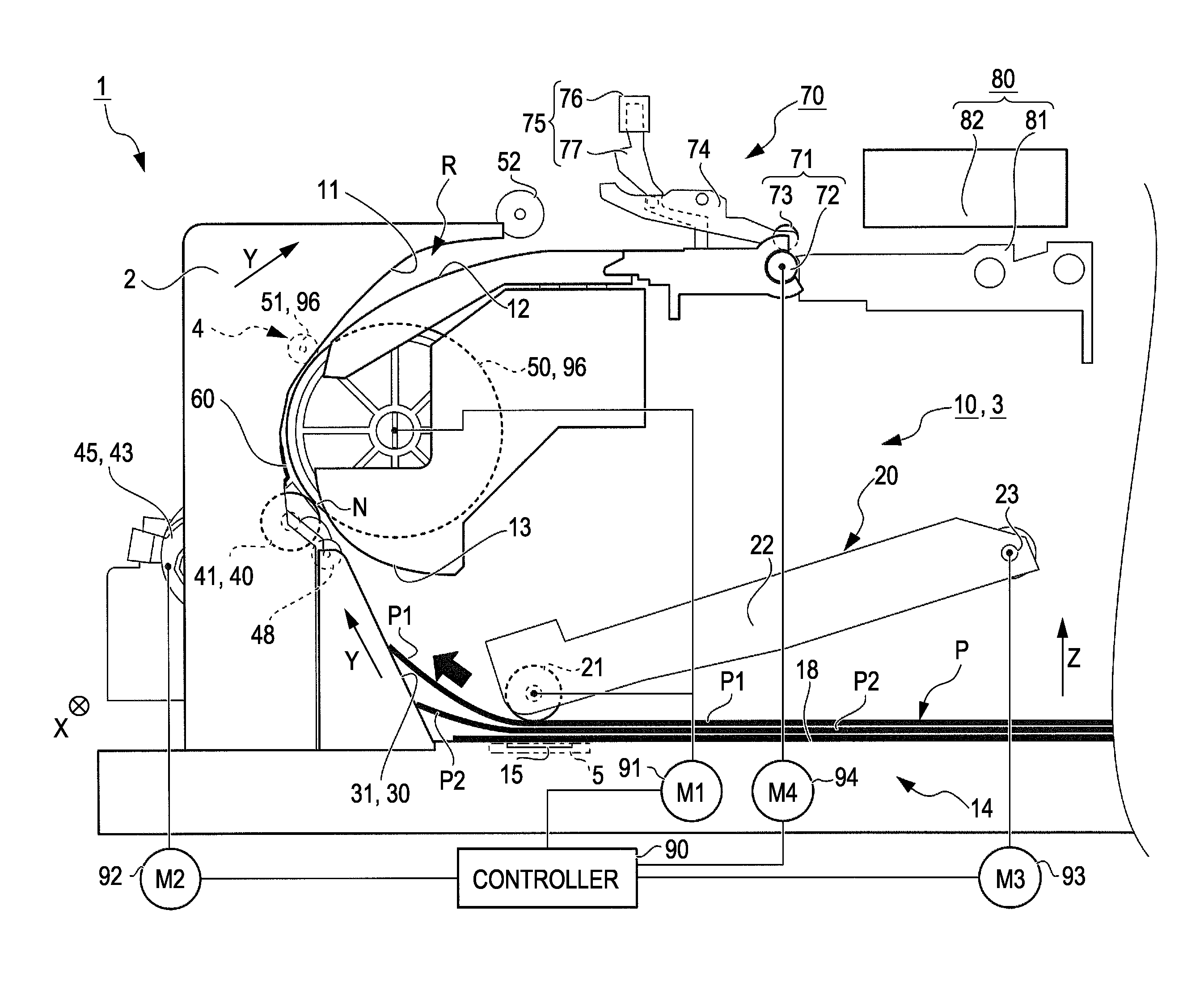
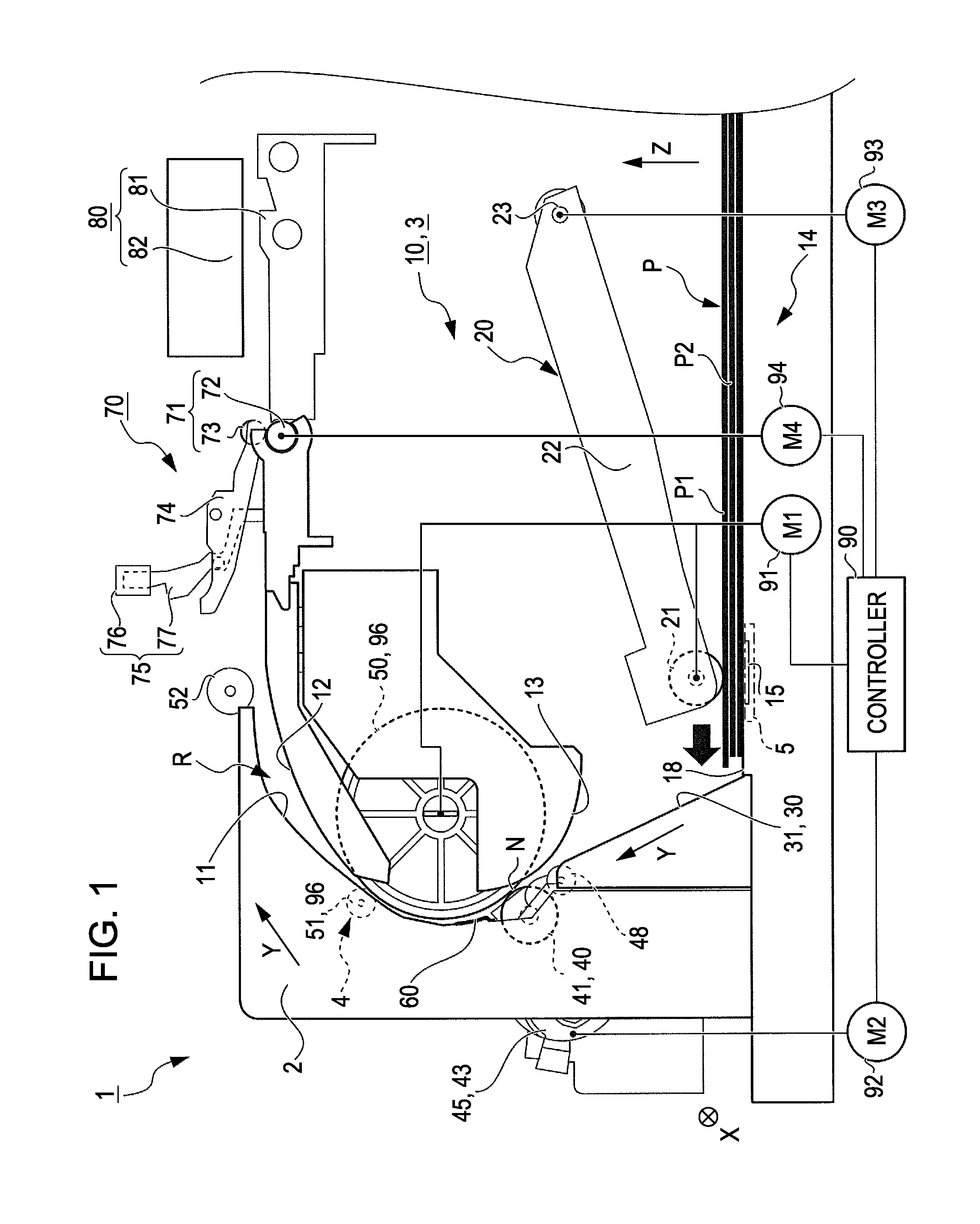
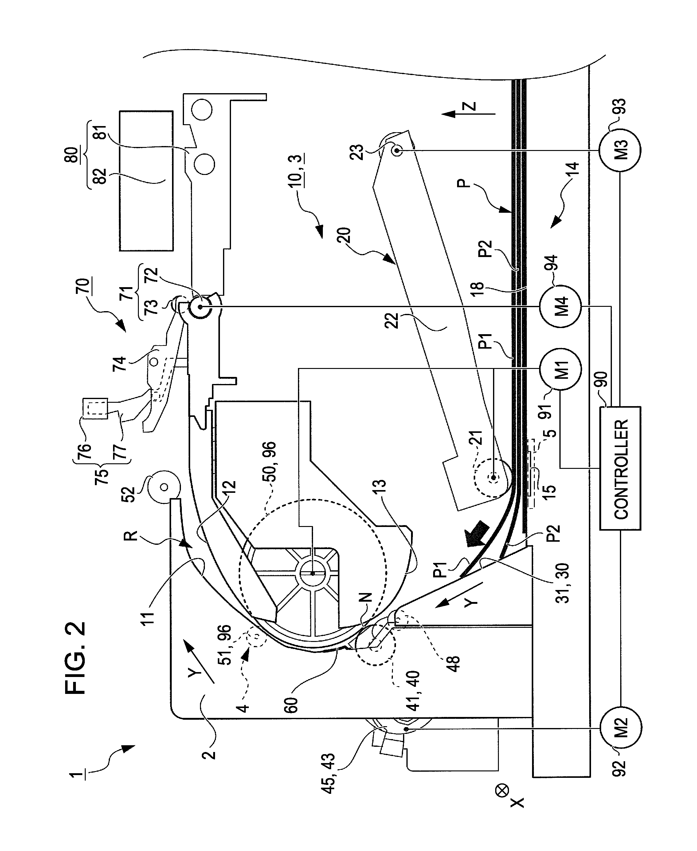
[0012]In addition, if the case where the number of remaining sheets is one sheet, it is possible to prevent the trailing end of the medium to be fed from coming into contact with the friction member when the final single sheet is reversely fed. Therefore, it is free from a risk in which the reverse feed of the medium to be fed is disturbed. That is, it can perform the reliable reverse feed.
[0035]In addition, the posture of the edge of the displacement member in the locked state is parallel with the posture of the top portion of the friction member. Therefore, it is possible to reliably prevent the trailing end of the medium to be fed from coming into contact with the friction member.

Problems solved by technology

In the case where the trailing end of final one remaining sheet of paper is reversely fed, since the trailing end of the paper comes into contact with the high-friction member depending up the size of the paper, it can disturb the reverse feed.
In particular, a problem likely happens in the case where a guide path of the paper from the pick-up to the pair of transport rollers is bent when seen at a lateral direction.
In this case, when the final single sheet is reversely fed, the trailing end of the medium to be fed may be caught by the stepped portion to disturb the reverse feed.

Method used


Image

  • Medium feeding device and recording apparatus
  • Medium feeding device and recording apparatus
  • Medium feeding device and recording apparatus

Examples


Embodiment Construction

[0056]An embodiment of the invention will now be described with reference to the accompanying drawings.

[0057]FIG. 1 is a side view illustrating the pick-up operation in an inside of an ink jet printer (hereinafter, referred to as “printer”) as an example of a recording apparatus or a liquid ejecting apparatus.

[0058]Herein, the liquid ejecting apparatus is not limited to a recording apparatus, such as an ink jet type recording apparatus, a copy machine or a facsimile machine, which executes a record on a material to be recorded by ejecting ink onto the material to be recorded, such as recording paper, from a recording head serving as a liquid ejecting head. Other examples of the liquid ejecting apparatus include an apparatus that attaches liquid for a specific application, instead of ink, to an ejecting target medium corresponding to the recording material by ejecting the liquid to the ejecting target medium from a liquid ejecting head corresponding to the recording head.

[0059]Exampl...


PUM


Abstract

A medium feeding device includes a first feeding unit feeds the medium to be fed to a downstream side of a feeding direction. A second feeding unit then feeds the medium to a upstream side and a downstream side on the basis of a feeding direction of the first feeding unit. A friction member is positioned opposite to the first feeding unit. A displacement member converts between a first state in which the displacement member protrudes upwardly in a stacked direction with respect to the friction member and a second state in which the displacement member retracts downwardly. The displacement member is set as the second state when one remaining sheet of the medium is fed to the downstream side by the first feeding unit, and the displacement member is set as the first state when a trailing end of the one remaining sheet passes through the friction member.

Description

BACKGROUND[0001]1. Technical Field[0002]The present invention relates to a medium feeding device including a placing plane, on which a medium to be fed is placed, a first feeding unit for feeding the medium to be fed, which is placed on the placing plane, to a downstream side of a feeding direction, a second feeding unit for feeding the medium to be fed, which is fed by the first feeding unit, to an upstream side and a downstream side of the feeding direction on the basis of the feeding direction of the first feeding unit, and a friction member installed at a position on the placing plane, which is opposite to the first feeding unit, and a recording apparatus including the medium feeding device.[0003]The recording apparatus used in herein is not limited to an ink jet printer, a wire dot printer, a laser printer, a line printer, a copy machine, and a facsimile machine.[0004]2. Related Art[0005]In the related art, as shown in JP-A-2008-094521, a printer serving as a recording apparatu...

Claims


Application Information

Patent Timeline
IPC IPC(8): B41J13/00B65H5/00
CPCB65H1/266B65H5/06B65H3/5261B65H3/56B65H3/66B65H5/062B65H7/02B65H9/008B65H2404/1442B65H2404/1531B65H2404/6111B65H2405/1116B65H2511/224B65H2511/514B65H2701/1311B65H3/0684B65H2220/02B65H2220/01
Inventor SHIOHARA, HIROSHI
Owner SEIKO EPSON CORP
Learn More