
Radiation therapy system with real time magnetic resonance monitoring

a real-time magnetic resonance monitoring and radiation therapy technology, applied in the field of radiation therapy, can solve the problems of reducing the effectiveness of cancer combating, harming malignant and healthy cells, and less well targeted radiation, and achieve the effect of shortening the radiation therapy session

Active Publication Date: 2011-04-14
KONINKLIJKE PHILIPS ELECTRONICS NV
View PDF6 Cites 34 Cited by
  • Summary
  • Abstract
  • Description
  • Claims
  • Application Information

AI Technical Summary

Benefits of technology

[0012]One advantage resides in providing for shorter radiation therapy sessions.

Problems solved by technology

Nonetheless, ionizing radiation is harmful to both malignant and healthy cells, and so precise spatial targeting of the radiation is important for limiting collateral damage to healthy tissue.
Registration errors result in less well targeted radiation therapy, which can reduce its effectiveness at combating the cancer and can increase collateral damage to healthy tissue.
Another problem is that the time between planning data acquisition and radiation treatment can be many days or even longer.
However, difficulties arise in performing concurrent imaging and radiation therapy.
Computed tomography (CT) scanners are not well suited for such concurrent operation, because it is difficult or impossible to physically arrange for the x-ray beam of the CT scanner to simultaneously probe the spatial region undergoing radiation therapy.
However, interference caused by the radiation therapy system has heretofore been found to prevent acquisition of quality MR images during the radiation therapy.
This means that radiation therapy is not performed during the imaging.
Even for rapid real-time three-dimensional imaging sequences, the number of imaging data sampling intervals is sufficiently large that the duty cycle of the radiation source under this approach is substantially extended, thus prolonging the therapy session.

Method used


Image

  • Radiation therapy system with real time magnetic resonance monitoring
  • Radiation therapy system with real time magnetic resonance monitoring
  • Radiation therapy system with real time magnetic resonance monitoring

Examples


Embodiment Construction

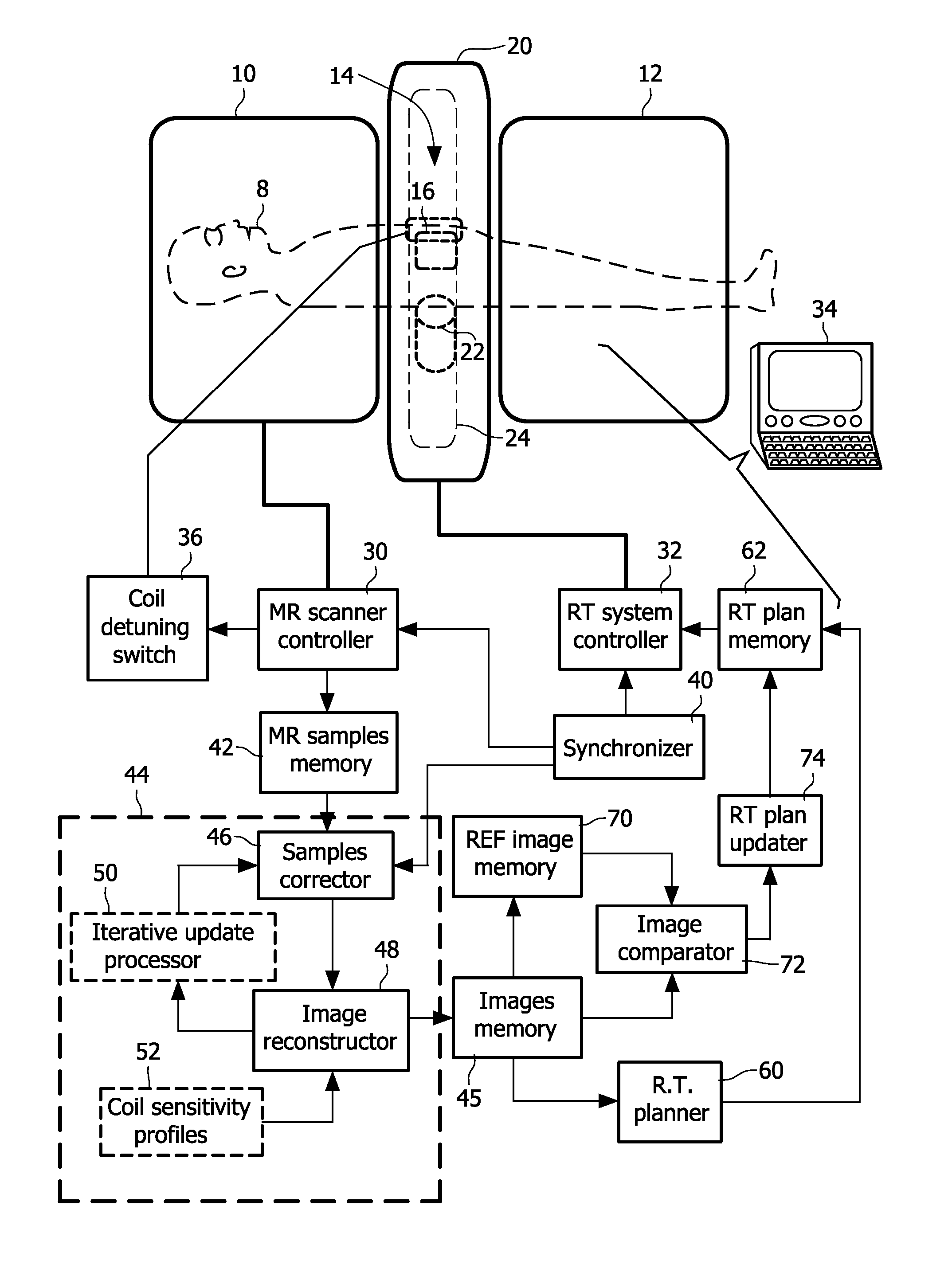
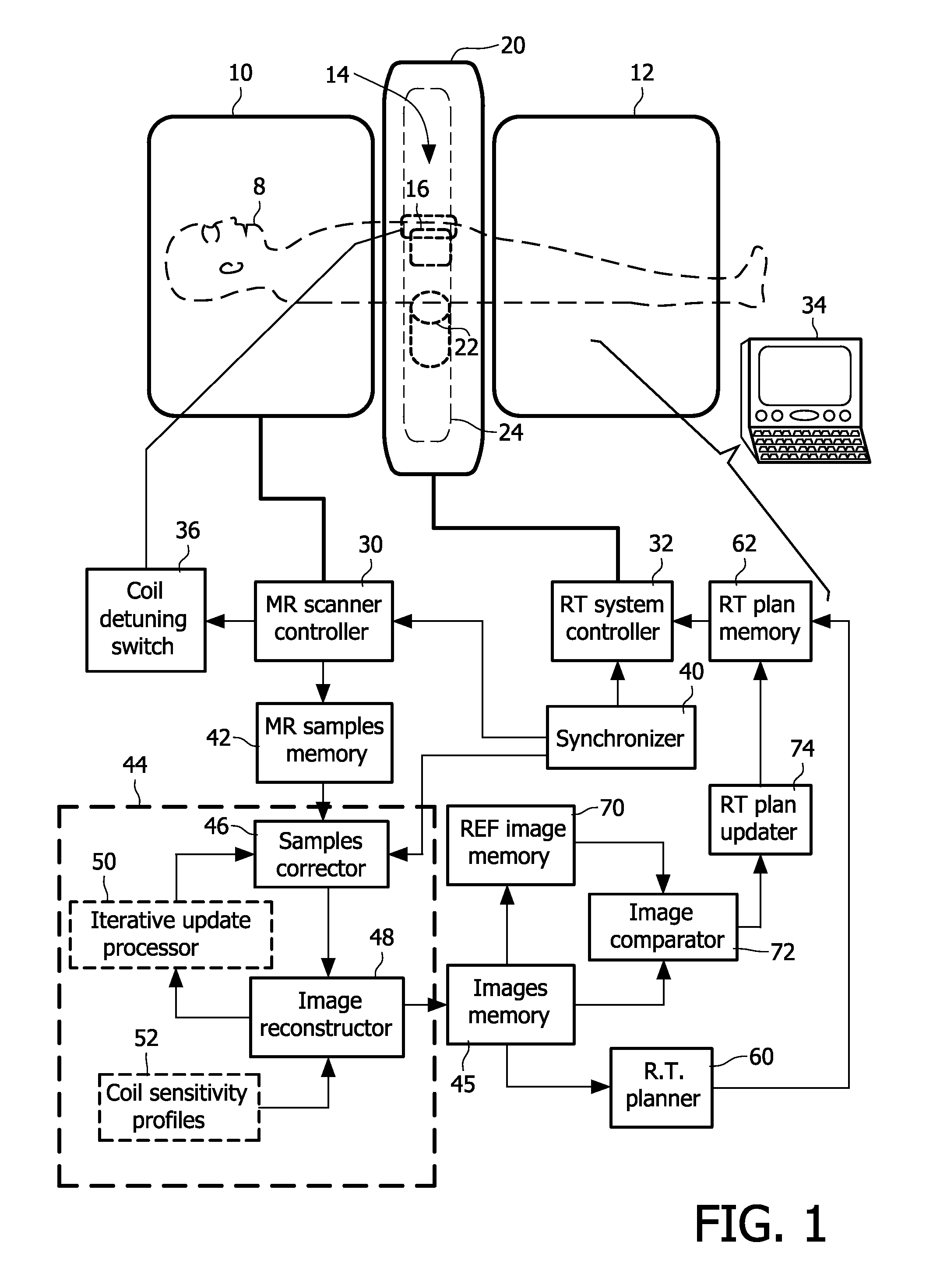
[0019]With reference to FIG. 1, a hybrid system receives a subject 8 (shown in phantom) for radiation therapy. The illustrated subject 8 is a human subject, but embodiments constructed to provide radiation therapy for animal subjects are also contemplated. The hybrid system includes a magnetic resonance (MR) scanner having a magnet formed of two magnet portions 10, 12 configured to have an annular gap 14 therebetween. The MR scanner includes other components such as magnetic field gradient coils (not shown, typically disposed within the magnet 10, 12) and one or more radio frequency coils such as a representative one or more local radio frequency coils 16 (shown in phantom).

[0020]A radiation therapy system includes a housing or other support or body 20 supporting a radiation source, such as a diagrammatically indicated linear accelerator (linac) 22 (shown in phantom) arranged to move or revolve around the subject 8 along a circumferential gantry or track 24 (shown in phantom) to ena...


PUM


Abstract

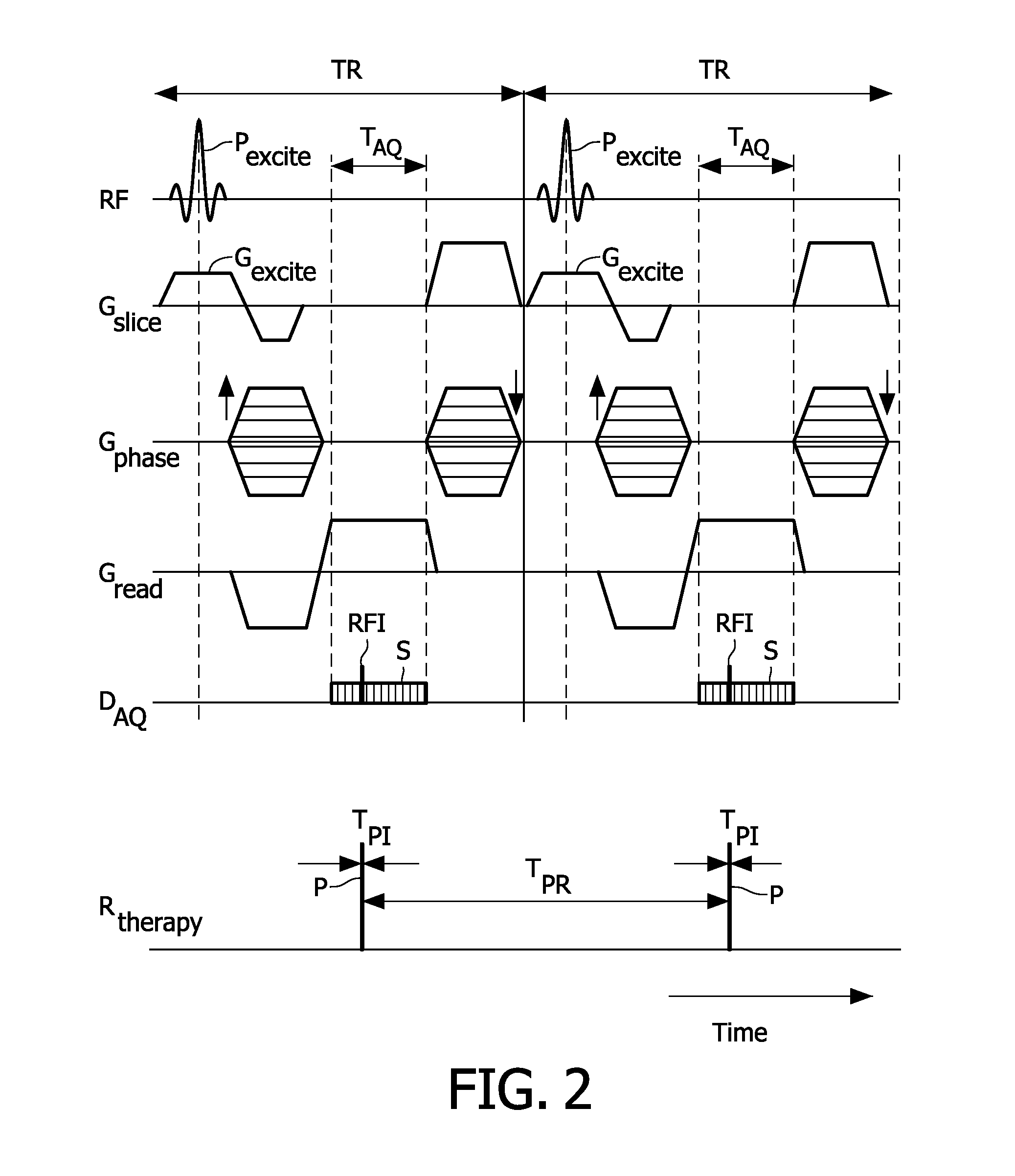
A radiation therapy system comprises: a radiation therapy subsystem (20, 22, 32) configured to perform radiation therapy by applying radiation pulses to a region of a subject at pulse intervals (Tpi); a magnetic resonance (MR) imaging subsystem (10, 16, 30, 36) configured to acquire a dataset of MR imaging data samples from the region of the subject over one or more MR sampling intervals (TAQ) that are longer than the pulse intervals, the one or more MR sampling intervals overlapping at least some of the pulse intervals; a synchronizer (40) configured to identify MR imaging data samples of the dataset whose acquisition times overlap pulse intervals; and a reconstruction processor (44) configured to reconstruct the dataset without the measured values for the MR imaging data samples identified as having acquisition times overlapping pulse intervals to generate a reconstructed MR image.

Description

FIELD OF THE INVENTION[0001]The following relates to the medical arts, imaging arts, magnetic resonance arts, and related arts. It finds particular application in radiation therapy and is described with particular reference thereto.BACKGROUND OF THE INVENTION[0002]In radiation therapy, spatially targeted dosages of ionizing radiation are applied to a tumor or other region containing cancerous or malignant tissue. Growing and rapidly multiplying cancer cells are often more susceptible to damage from ionizing radiation as compared with normal cells, and so enforced by the higher dosage administered by proper planning, the applied radiation preferentially kills cancerous or malignant tissue. Nonetheless, ionizing radiation is harmful to both malignant and healthy cells, and so precise spatial targeting of the radiation is important for limiting collateral damage to healthy tissue. Damage to healthy tissue is also typically controlled by performing the radiation therapy in a series of s...

Claims


Application Information

Patent Timeline
IPC IPC(8): A61B5/055A61N5/00
CPCA61B5/055A61N5/1038A61N5/1049A61N5/1067G01R33/5611G01R33/4808G01R33/56G01R33/5608A61N2005/1055
Inventor BOERNERT, PETEROVERWEG, JOHANNES ADRIANUS
Owner KONINKLIJKE PHILIPS ELECTRONICS NV
Learn More