Robot parts assembly on a workpiece moving on an assembly line

a technology for assembly lines and workpieces, applied in the direction of programmed manipulators, programme control, instruments, etc., can solve the problems of increasing the number and complexity of assembly tasks performed by industrial robots, saving huge amounts of time and resources, and difficult for conventional industrial robots to adapt to any sort of chang

Active Publication Date: 2011-04-14
ABB RES LTD
View PDF18 Cites 81 Cited by
  • Summary
  • Abstract
  • Description
  • Claims
  • Application Information

AI Technical Summary

Problems solved by technology

Assembly tasks using industrial robots have increased in both number and complexity over the years because of the increasing requirements of product quality and quantity.
However, robots performing assembly tasks are still a small portion of total robot sales each year.
One of the main reasons is that it is difficult for conventional industrial robots to adjust to any sort of change such as those that may occur when the workpiece on which the parts are to be assembled is moving on an assembly line.
Compared to stop-station assembly, that is, an assembly which is performed when the parts are stationary, moving line assembly can save huge amounts of time and resources.
This could cause tracking errors and eventually the failure of an assembly process.
Because the stereo vision system requires high quality cameras and accurate calibrations, these systems are costly, error prone and not robust enough for daily use in the workshop.
The complicated computation for determining the position / orientation of an object makes this system difficult to implement in real time applications, especially for fast motion tracking.
Also visual serving alone could cause damage to the final products if the stereo vision system malfunctions.

Method used


Image

  • Robot parts assembly on a workpiece moving on an assembly line
  • Robot parts assembly on a workpiece moving on an assembly line
  • Robot parts assembly on a workpiece moving on an assembly line

Examples


Embodiment Construction

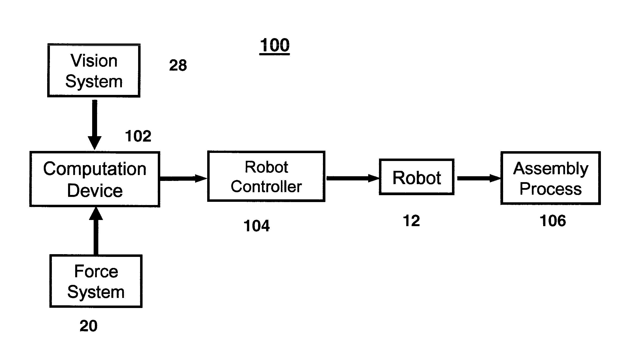
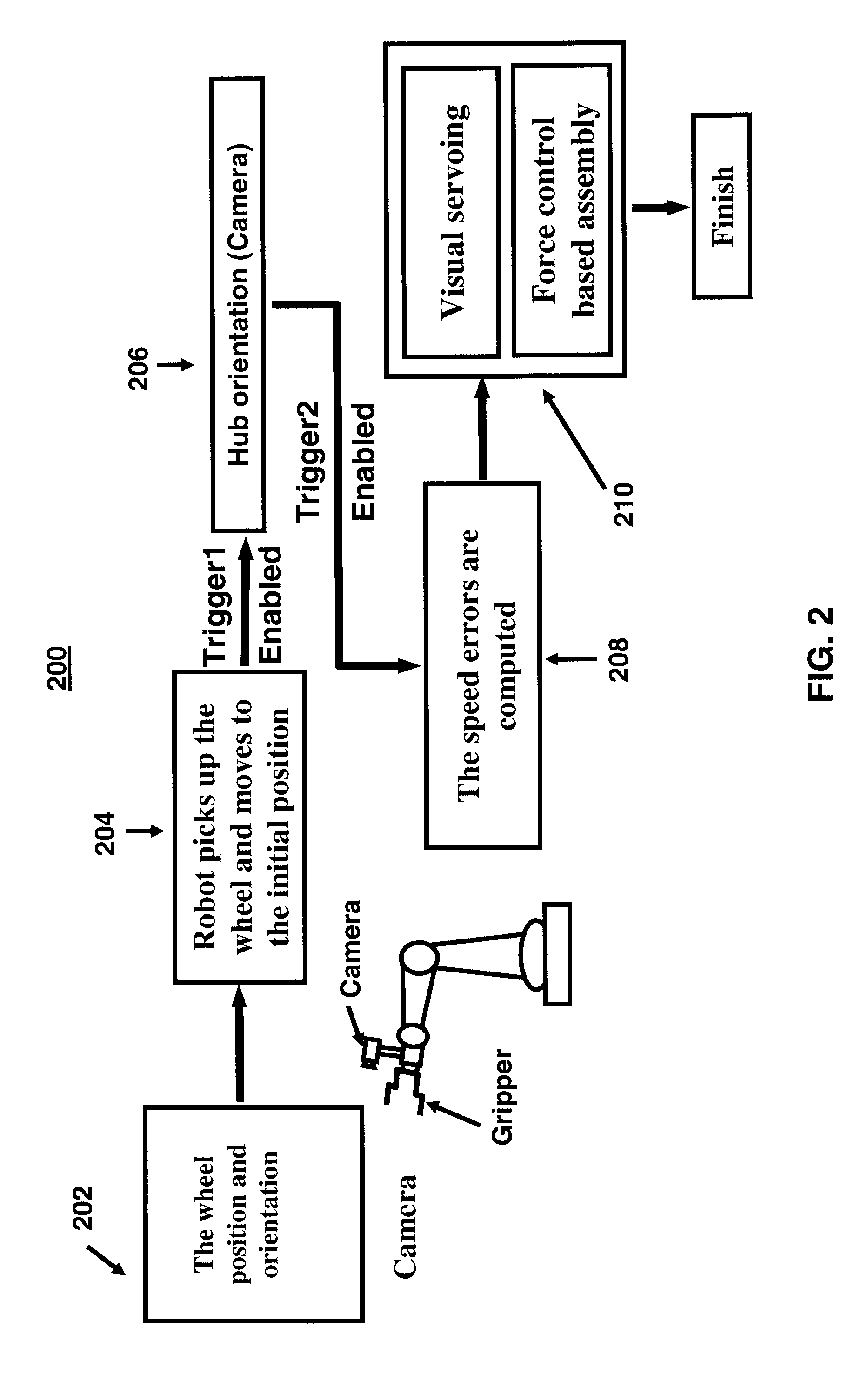
[0032]There is described herein a method and apparatus for controlling an industrial robot to perform the assembly of a part to a workpiece based on the synergistic combination of vision, force and position as the feedback information to control the robot motion while the workpiece is moving randomly. The speed errors are computed and the speed of the robot is controlled such that the tool that holds the part to be assembled to the moving workpiece tracks the motion of the randomly moving workpiece. A single camera with simple calibration combined with force control is used. As is described in more detail below, force control is applied to control the motion of the robotic system to perform the assembly task on the randomly moving workpiece.

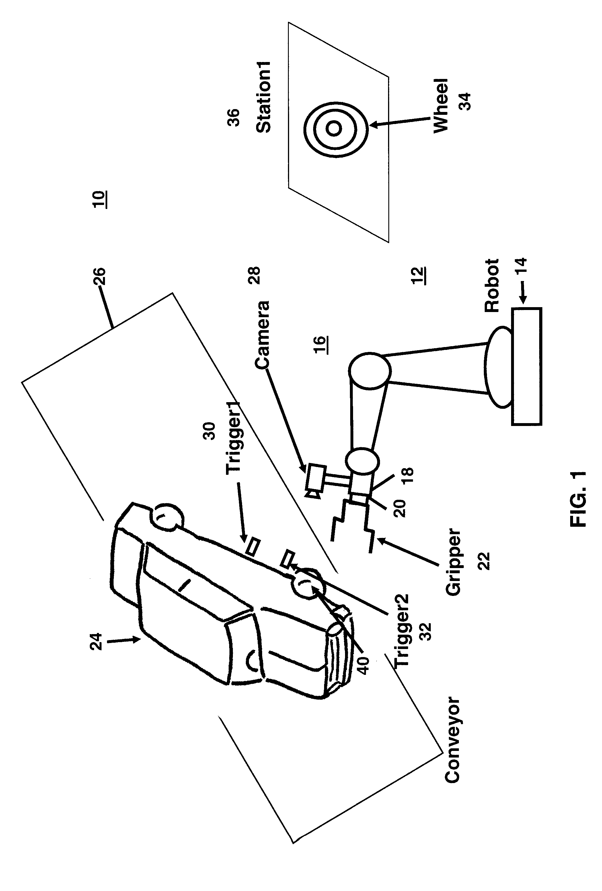
[0033]The method and apparatus is described below, by way of example and not of limitation, in connection with the process of loading a wheel on the hub of a motor vehicle moving on an assembly line. As is described below, in this example:

[0034]1...


PUM


Abstract

An industrial robot is used to assemble a part to a predetermined location on a randomly moving workpiece. The workpiece may be an automobile on an assembly line and the part may be a wheel (a tire mounted on a rim) to be assembled on one of the wheel hubs of the automobile. The robot has mounted on it a camera, a force sensor and a gripper to grip the part. After the robot grips the part, signals from both the force sensor and vision are used by a computing device to move the robot to a position where the robot can assemble the part to the predetermined location on the workpiece. The computing device can be the robot controller or a separate device such as a PC that is connected to the controller.

Description

FIELD OF THE INVENTION[0001]This invention relates to the use of robots for assembly of parts on a workpiece that is moving randomly on an assembly line.DESCRIPTION OF THE PRIOR ART[0002]Assembly tasks using industrial robots have increased in both number and complexity over the years because of the increasing requirements of product quality and quantity. However, robots performing assembly tasks are still a small portion of total robot sales each year. One of the main reasons is that it is difficult for conventional industrial robots to adjust to any sort of change such as those that may occur when the workpiece on which the parts are to be assembled is moving on an assembly line. Therefore, more intelligent industrial robotic systems are rapidly expanding the realms of possibility in assembly applications because they can perform assembly tasks with high autonomy and adaptability to the environments.[0003]Moving line assembly, that is an assembly of parts performed while the workp...

Claims


Application Information

Patent Timeline
Patent Type & Authority Applications(United States)
IPC IPC(8): B25J9/10B25J13/02B25J19/04
CPCB25J9/1697G05B2219/45021G05B2219/40554G05B2219/39387
Inventor CHEN, HEPINGZHANG, GEORGEFUHLBRIGGE, THOMAS A.
Owner ABB RES LTD
Why Eureka
Try Eureka