
Torque control device for internal combustion engine

a technology of torque control and internal combustion engine, which is applied in the direction of electric control, machines/engines, instruments, etc., can solve the problems of ineffective time (i.e., the time at which the acceleration does not appropriately rise up in correspondence with the acceleration instruction) and does not increase, so as to prevent response deterioration and fuel consumption deterioration, appropriately suppressing acceleration shock occurren

Inactive Publication Date: 2011-04-14
TOYOTA JIDOSHA KK
View PDF1 Cites 14 Cited by
  • Summary
  • Abstract
  • Description
  • Claims
  • Application Information

AI Technical Summary

Benefits of technology

The present invention provides a torque control device for an internal combustion engine that can prevent response deterioration and fuel consumption deterioration during acceleration and appropriately suppress acceleration shock occurrence. The device includes a driving-system torque calculation unit and a torque control unit. The driving-system torque calculation unit calculates the torque operating on the driving system for transmitting the torque to the driving wheels, based on the requested torque at the time of acceleration. The torque control unit controls the torque so that the gradient of the driving-system torque becomes equal to or smaller than a predetermined value. This prevents the driving system from twisting excessively and allows for an appropriate response to acceleration requests. The device can also change the predetermined value based on the driver's request or the vehicle's driving mode. Overall, this invention helps to maintain the driving-system twisting amount constant, preventing deterioration of the response to acceleration requests and appropriately suppressing acceleration shock.

Problems solved by technology

In addition, since the control to make the torque of the internal combustion engine down is not always executed on condition that the acceleration shock occurs, an ineffective time (i.e., the time at which the acceleration does not appropriately rise up in correspondence with an acceleration instruction) does not increase.

Method used


Image

  • Torque control device for internal combustion engine
  • Torque control device for internal combustion engine
  • Torque control device for internal combustion engine

Examples


first embodiment

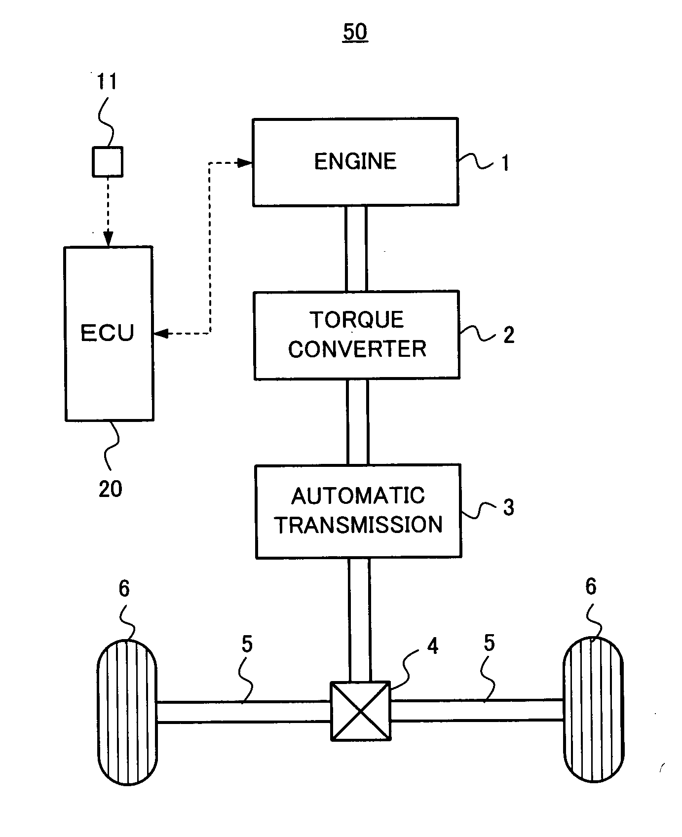
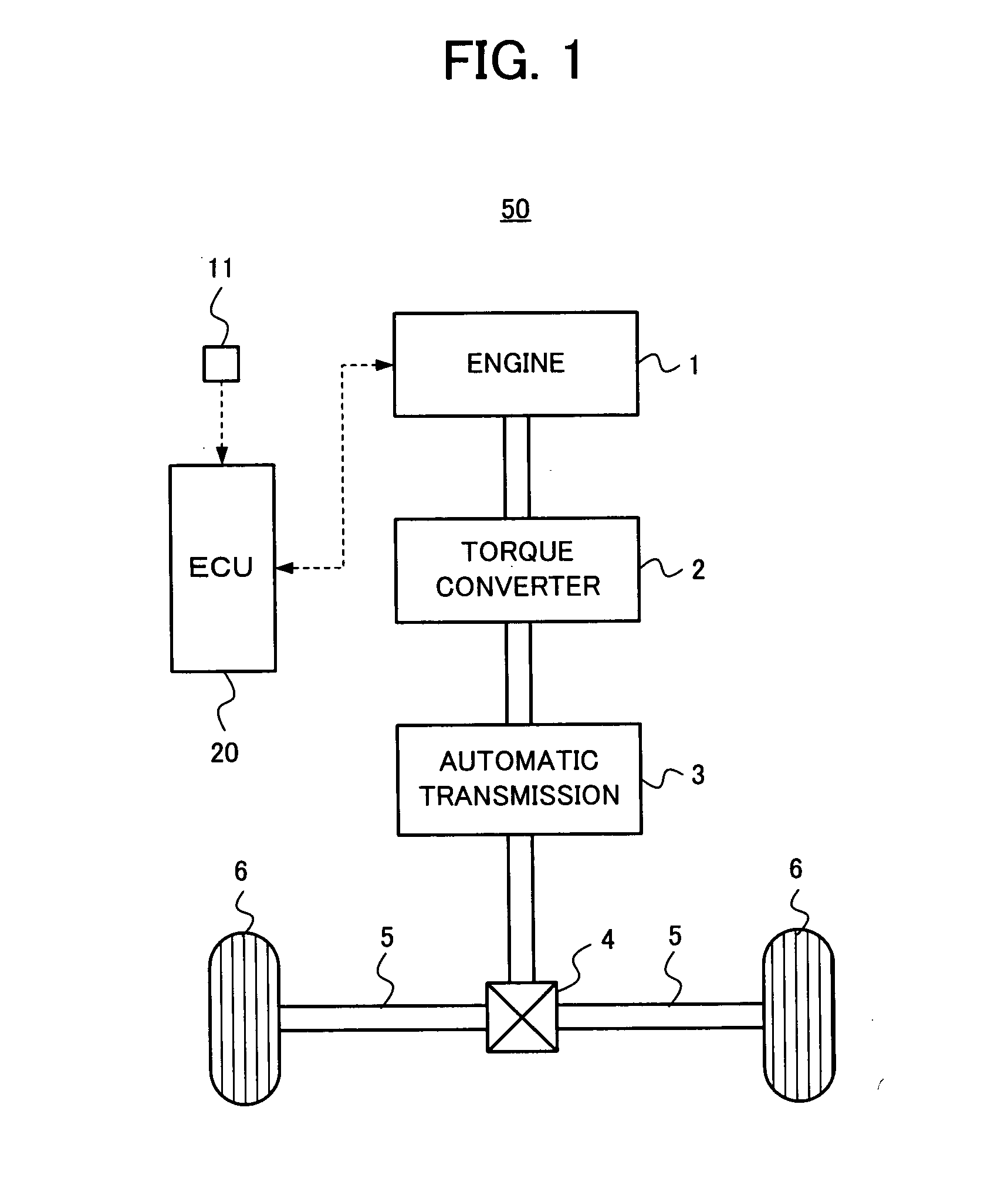
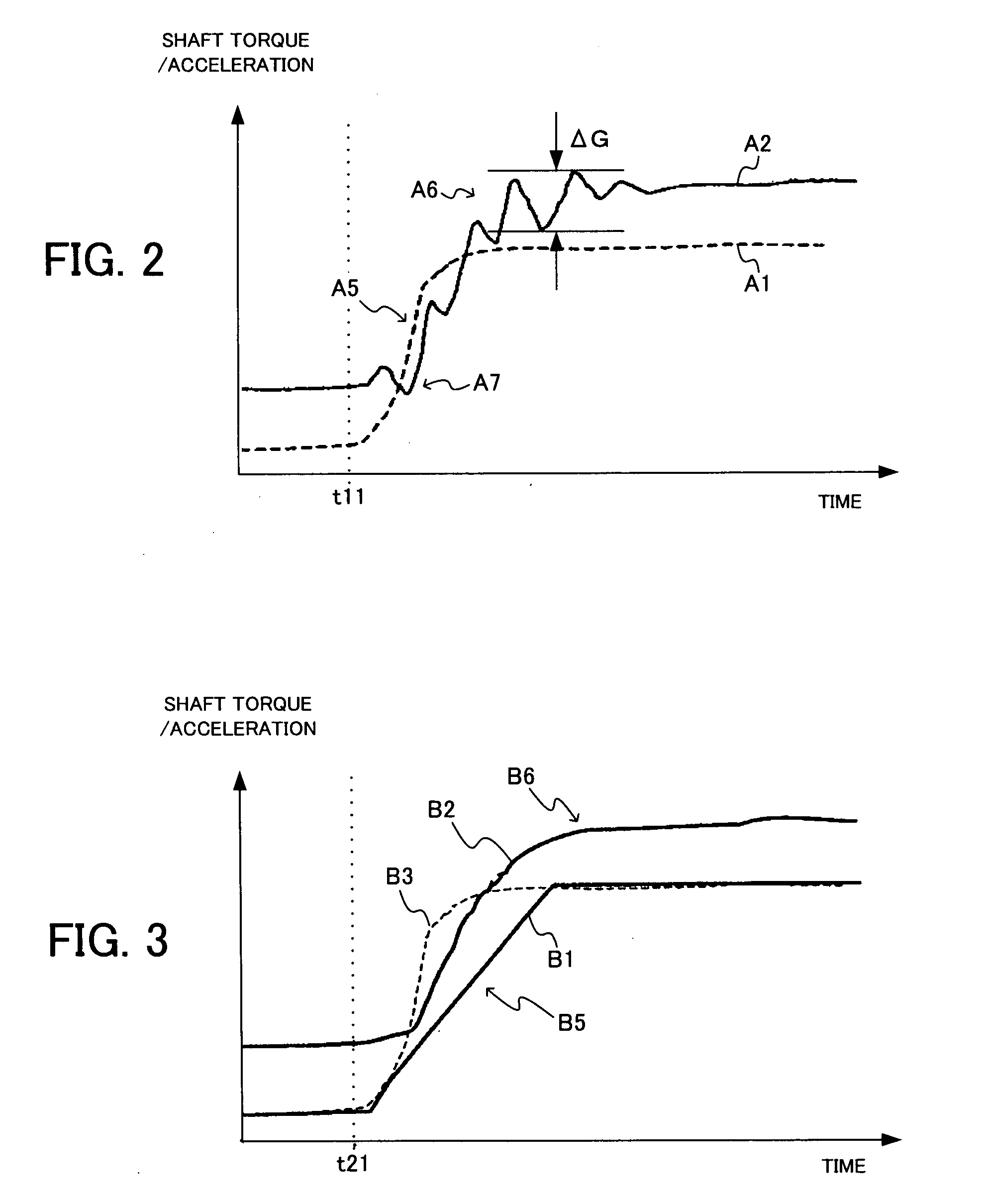
[0049]In a first embodiment, the ECU 20 obtains the shaft torque from the requested torque at the time of acceleration. Then, when the shaft torque gradient becomes larger than the predetermined value (i.e., the maximum allowable shaft torque gradient), the ECU 20 executes the torque control of the engine 1 so that the shaft torque gradient is limited to the maximum allowable shaft torque gradient. Concretely, the ECU 20 calculates the requested torque based on the acceleration instruction of the driver, which is obtained by the accelerator opening degree sensor 11, and obtains the shaft torque in consideration of the requested torque, the gear stage of the automatic transmission 3 and the gear ratio of the differential gear 4. Then, the ECU 20 obtains the shaft torque gradient from the shaft torque, which corresponds to observing the shaft torque and obtaining the shaft torque gradient. When the shaft torque gradient becomes larger than the maximum allowable shaft torque gradient, ...

second embodiment

[0058]Next, a description will be given of a second embodiment of the present invention. In the second embodiment, the torque control of the engine 1 is executed so that the shaft torque gradient is maintained equal to or smaller than the maximum allowable shaft torque gradient during the acceleration, similarly to the above-mentioned first embodiment. However, the second embodiment is different from the first embodiment in that the maximum allowable shaft torque gradient is changed in correspondence with the request of the driver. Concretely, in the second embodiment, the ECU 20 uses the drive mode which the driver sets in order to adjust the drivability, as the request of the driver, and changes the maximum allowable shaft torque gradient in correspondence with the drive mode. That is, the ECU 20 changes the aimed shock amount in correspondence with the set drive mode.

[0059]A description will be given of an example of a method of changing the maximum allowable shaft torque gradien...

third embodiment

[0066]Next, a description will be given of a third embodiment of the present invention. In the third embodiment, the torque control of the engine 1 is also executed so that the shaft torque gradient is maintained equal to or smaller than the maximum allowable shaft torque gradient during the acceleration, similarly to the above first and second embodiments. Also, the maximum allowable shaft torque gradient is changed in correspondence with the request of the driver, similarly to the second embodiment. However, the third embodiment is different from the second embodiment in that the ECU 20 uses, as the request of the driver, the accelerator opening speed (i.e., accelerator stamping speed) and the maximum allowable shaft torque gradient is changed in correspondence with the accelerator opening speed. Namely, the ECU 20 changes the aimed shock amount in correspondence with the accelerator opening speed.

[0067]A description will be given of an example of a method of changing the maximum ...


PUM


Abstract

In a torque control device for an internal combustion engine, a driving-system torque calculation unit calculates a driving-system torque operating on a driving system, based on a requested torque at a time of acceleration. A torque control unit executes torque control so that a gradient of the driving-system torque becomes equal to or smaller than a predetermined value, based on the driving-system torque calculated by the driving-system torque calculation unit. Thereby, since an amount of twist of the driving system can be maintained equal to or smaller than a predetermined value, repetitive shock can be suppressed, and acceleration shock can be effectively suppressed, too. Response deterioration and fuel consumption deterioration at the time of acceleration can be prevented.

Description

TECHNICAL FIELD[0001]The present invention relates to torque control of an internal combustion engine in order to suppress shock occurring at a time of acceleration.BACKGROUND TECHNIQUE[0002]A technique of this kind is described in Patent Reference 1, for example. In Patent Reference 1, there is disclosed a technique of executing phase delay control of ignition timing to suppress acceleration shock occurring due to a twisting vibration of a driving system (corresponding to a power transmission system which transmits output of the internal combustion engine to driving wheels) at the time of acceleration. In Patent Reference 2, there is disclosed a technique of predicting the twisting vibration in the driving system at the time of acceleration and executing control of throttle opening degree and ignition timing in order to suppress the predicted vibration component. In Patent Reference 3, there is disclosed a technique associated with the present invention.[0003]In the techniques of P...

Claims


Application Information

Patent Timeline
Patent Type & Authority Applications(United States)
IPC IPC(8): F16H59/14
CPCB60W10/06B60W30/20B60W2710/0672B60W2710/1055F02D41/0002F02D2400/12F02D41/10F02D2200/602F02D2250/18F02D2250/26F02D2250/28F02D41/0225
Inventor ASO, KOJI
Owner TOYOTA JIDOSHA KK
Learn More