Support structure for flat-plate heat pipe

a technology of supporting structure and heat pipe, which is applied in the direction of heat exchangers, indirect heat exchangers, light and heating apparatus, etc., can solve the problems of difficult to provide sufficient working fluid to go back the evaporating end, non-uniform distribution of thermal flux over the surface of heat-generating electronic components, and increasing the problem of heat dissipation, etc., to achieve better thermal uniformity and better heat dissipation

Inactive Publication Date: 2011-04-21
ASIA VITAL COMPONENTS SHENZHEN CO LTD
View PDF3 Cites 20 Cited by
  • Summary
  • Abstract
  • Description
  • Claims
  • Application Information

AI Technical Summary

Benefits of technology

[0012]The main body has a top section, a second side section and a bottom section opposite to the top section. The top section and the bottom section respectively abut against the first and second flat plates. The fitting bodies are stacked and fitted around th

Problems solved by technology

During continuous promotion of the performances of electronic products, the issue of heat dissipation has become more and more critical.
Due to different performances of different electronic components, the thermal flux is non-uniformly distributed over the surfaces of the heat-generating electronic components.
However, there are some problems with the above structure.
In this case, it is hard to provide sufficient working fluid to go back the evaporating end.
As a result, the heated end of the heat pipe may dry out to lead to poor heating uniformity and po

Method used


Image

  • Support structure for flat-plate heat pipe
  • Support structure for flat-plate heat pipe
  • Support structure for flat-plate heat pipe

Examples


first embodiment

[0022]Please refer to FIGS. 3, 4 and 5. the support structure for flat-plate heat pipe of the present invention includes a main body 3 and a fitting body 4. The fitting body 4 has at least one open side 41 and a first side section 42 connected with the open side 41. The first side section 42 has a capillary structure 421 formed on a periphery of the first side section 42. The capillary structure 421 can be a porous structure in the form of metal spring, metal mesh or sintered metal powder. The capillary structure 421 has flow-guiding ability and provides multiple backflow channels. Accordingly, the capillary structure 421 serves to guide the fluid to quickly flow from the colder portion back to the heated portion so as to enhance fluid circulating rate and increase flow amount and prevent the fluid flowing within the heated portion from drying out. Alternatively, the periphery of the first side section 42 can be directly formed with channel-shaped or porous capillary structure 421 ...

second embodiment

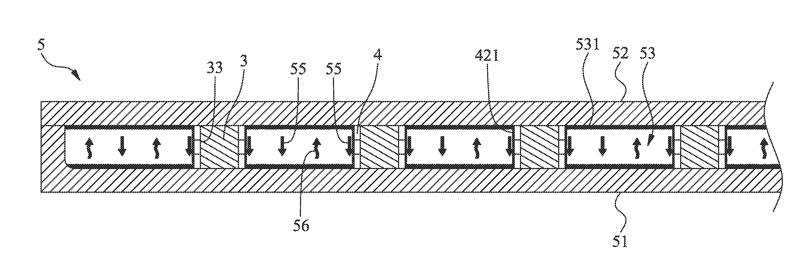
[0030]FIGS. 6 to 8 show the present invention, in which several fitting bodies 4 are stacked and fitted around the main body 3. To speak more specifically, the fitting bodies 4 are sequentially fitted around the main body 3 with the total of the heights of the fitting bodies 4 equal to the height of the main body 3. In this case, the fitting bodies 4 and the main body 3 fitted therein are arranged between the first and second flat plates 51, 52 in abutment therewith. In this embodiment, the number of the fitting bodies 4 is, but not limited to, three. Alternatively, there can be four, five, six or more fitting bodies in accordance with the height of the main body 3. That is, the number of the fitting bodies 4 is determined by the actual height of the main body 3.

[0031]According to the aforesaid, the support structure for flat-plate heat pipe of the present invention has the following advantages:[0032]1. The present invention has better heat dissipation effect.[0033]2. The present in...


PUM


Abstract

A support structure for flat-plate heat pipe, including a main body and a fitting body. The fitting body has at least one open side and a first side section connected with the open side. The first side section has a capillary structure formed on a periphery of the first side section. The first side section and the open side together define a space for fixedly fitting the main body therein. By means of the capillary structure of the first side section of the fitting body, the circulating rate of a working fluid flowing within the flat-plate heat pipe is increased to achieve better heat dissipation effect and better thermal uniformity.

Description

FIELD OF THE INVENTION[0001]The present invention relates to a flat-plate heat pipe, and more particularly to an improved support structure for flat-plate heat pipe including a main body and a fitting body in which the main body is fitted. The fitting body has a first side formed with a capillary structure. By means of the capillary structure of the first side section of the fitting body, the circulating rate of a working fluid flowing within the flat-plate heat pipe is increased to achieve better heat dissipation effect and better thermal uniformity.BACKGROUND OF THE INVENTION[0002]Following the rapid progress of industrial technique, there is a trend in electronic products of miniaturized volume, light weight, low power consumption, high performance and high efficiency. Therefore, the working rate of the electronic products is enhanced and the number of electronic components per unit volume is increased. During continuous promotion of the performances of electronic products, the i...

Claims


Application Information

Patent Timeline
IPC IPC(8): F28D15/02F28F9/013
CPCF28D15/046F28D15/0233
Inventor YANG, HSIUWEI
Owner ASIA VITAL COMPONENTS SHENZHEN CO LTD
Why Eureka
Try Eureka