
Mobile water treatment

a technology of mobile water treatment and water transport, which is applied in the direction of water/sewage treatment, cartridge filters, transportation items, etc., can solve the problems of hydraulic fracture process that requires millions of gallons of water per well, large amount of water used in hydraulic fracture process, and large amount of water used in drilling wells. , to achieve the effect of reducing the overall water procurement, transportation, disposal and filtering costs

Active Publication Date: 2011-04-21
IBEX
View PDF8 Cites 26 Cited by
  • Summary
  • Abstract
  • Description
  • Claims
  • Application Information

AI Technical Summary

Benefits of technology

[0009]The inventors recognized that what is needed is a process for transporting and filtering water that reduces the overall water procurement, transport, disposal, and filtering costs.
[0011]The mobile water treatment apparatus described herein is designed to address these issues. In particular, the mobile water treatment apparatus described herein is adapted to both transport and filter a fluid retrieved from a first location to a second location, thus avoiding transportation costs attributed to moving water to and from an off-site filtration facility.

Problems solved by technology

Accordingly, drilling a well may require hundreds of thousands of gallons of water.
Furthermore, the process of hydraulic fracture uses a large amount of water.
Accordingly, the hydraulic fracture process requires millions of gallons of water per well.
However, water recovered from the well is unclean and filled with hydrocarbons, suspended solids, heavy metals, and bacteria.
The process of using trucks to transport the water increases the volume of traffic on roads and requires fossil fuels to power the trucks.
Similarly, a company may construct a piping system to pump the water through the piping system to and from a filtering location, but such a piping system is a considerable expense.
However, this requires additional expense to set up a filtering facility.
Historically, filtration systems have been too large or too heavy to allow for easy transport.
In particular, it is identified that it is inefficient for an oil and gas company to transport water to and from a filtration facility located a distance away from the well site.
It is also inefficient to maintain separate and distinct water transport and water filtration steps.

Method used


Image

  • Mobile water treatment
  • Mobile water treatment
  • Mobile water treatment

Examples


Embodiment Construction

[0024]Referring now to the drawings, wherein like reference numerals designate identical or corresponding parts throughout the several views.

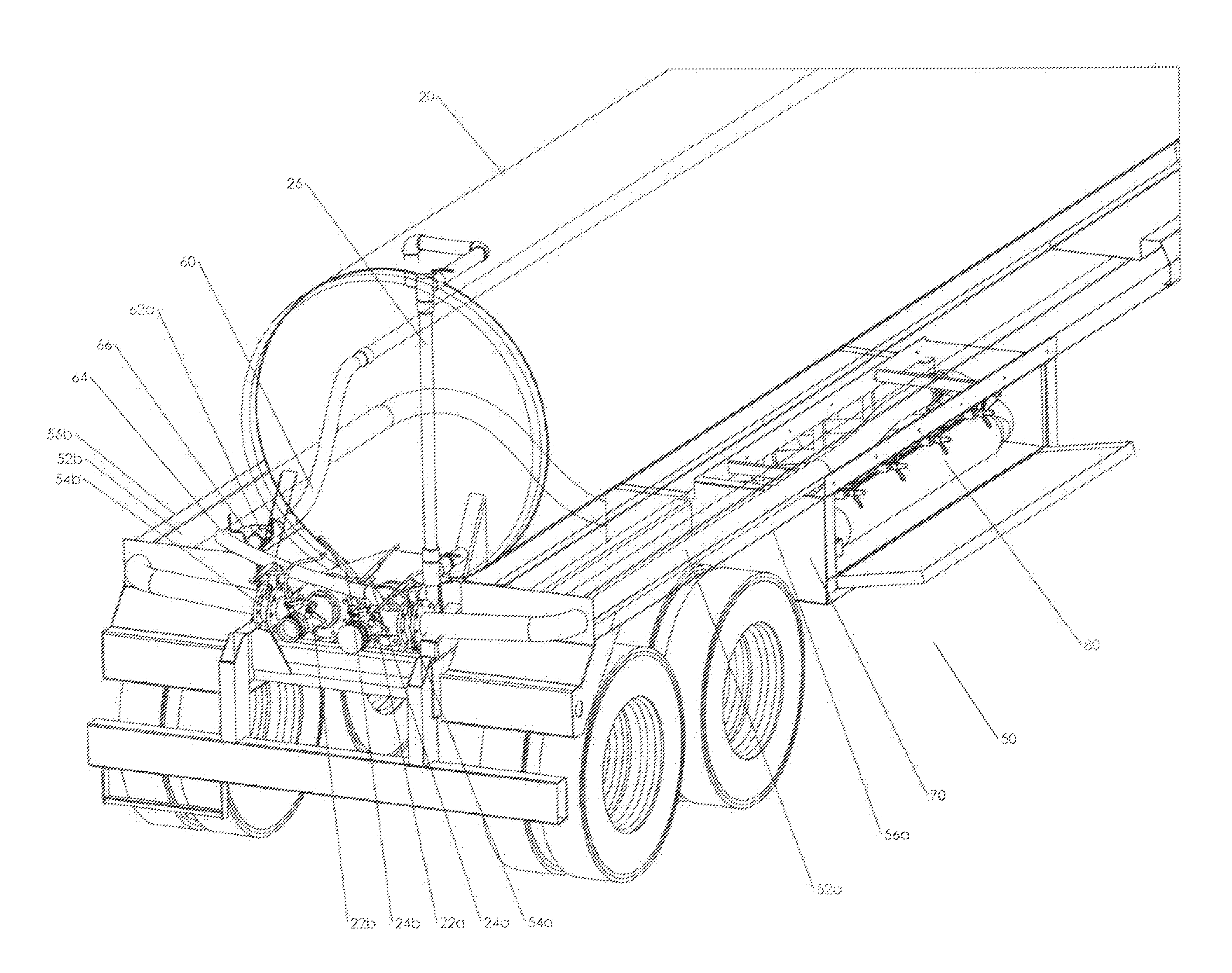
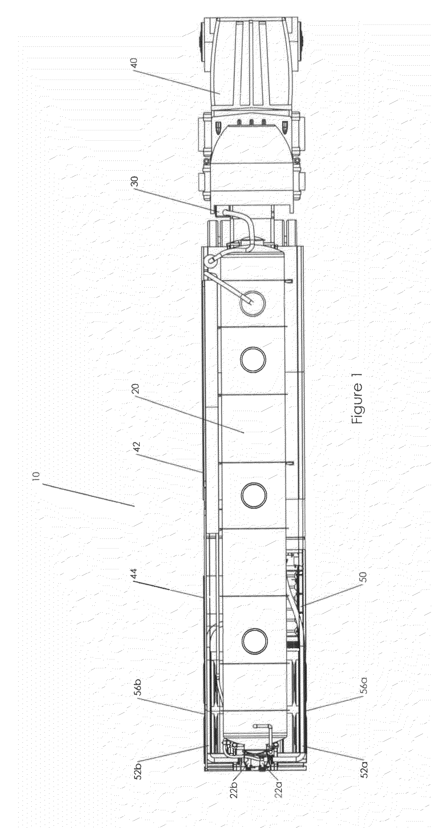
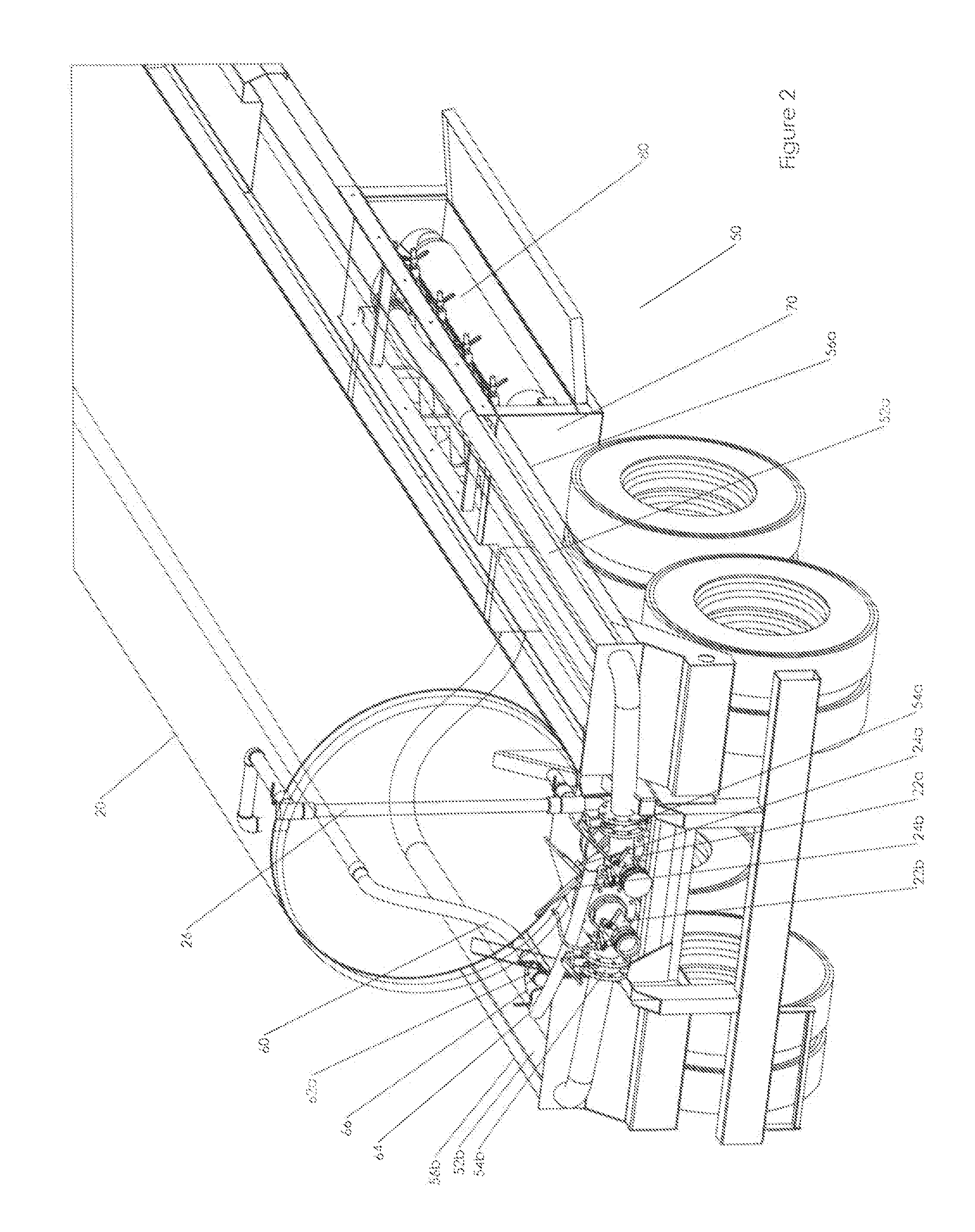
[0025]FIG. 1 is a plan view of a mobile water treatment apparatus 10. Mobile water treatment apparatus 10 may include a motor vehicle 40 including a trailer 42, a storage tank 20, a vacuum / pump system 30, and filtration system 50 along with their respective connections. It should be appreciated that the vacuum / pump system 30, filtration system 50, storage tank 20 and their respective connections may be secured to trailer 42. Vacuum / pump system 30 may create a positive or negative pressure within storage tank 20 to on-load or off-load fluid into storage tank 20. In one aspect of the invention, vacuum / pump system 30 may be powered by motor vehicle 40. In an alternate aspect of the invention, vacuum / pump system 30 may be separate from motor vehicle 40 and may include its own power generating device. When vacuum / pump system 30 creates a negative pr...


PUM

PropertyMeasurementUnit
pressureaaaaaaaaaa
pressureaaaaaaaaaa
pressuresaaaaaaaaaa

Abstract

A mobile water treatment apparatus to on-load a dirty fluid into a storage container attached to a motor vehicle and transport the fluid in the storage container from a first location and to a second location where the fluid is filtered by a filtration system attached to the motor vehicle. The filtered fluid is discharged from the mobile water treatment apparatus at the second location.

Description

BACKGROUND[0001]1. Field of the Disclosure[0002]This disclosure relates generally to a fluid transport and filtration system, and more particularly to a water transport and filtration system for oil and gas well operations.[0003]2. Description Of The Related Art[0004]The “background” description provided herein is for the purpose of generally presenting the context of the disclosure. Work of the presently named inventors, to the extent it is described in this background section, as well as aspects of the description which may not otherwise qualify as prior art at the time of filing, are neither expressly nor impliedly admitted as prior art against the present invention.[0005]Water is essential to the oil and gas industry. In an oil or gas well, water is used to cool and lubricate the drillbit and to extract debris. Accordingly, drilling a well may require hundreds of thousands of gallons of water. Water is also recovered as a byproduct of oil and gas wells as produced water.[0006]Fu...

Claims


Application Information

Patent Timeline
Patent Type & Authority Applications(United States)
IPC IPC(8): C02F1/00B01D29/00B01D29/50
CPCC02F1/001C02F1/004C02F1/38C02F2201/008C02F1/463C02F2103/10C02F1/44Y10T137/6855Y10T137/6881
Inventor KENNEDY, JAMES VANCEWESCOTT, BRON DAVIDSANFORD, STANLEY LAMAR
Owner IBEX
Learn More