Band rejection filter

a filter and band technology, applied in the field of band rejection filters, can solve the problems of deteriorating sensitivity of increasing the area in which the ladder circuit occupies, and affecting the tv tuner for receiving the broadcasting service for mobile devices. , to achieve the effect of large attenuation amount and high filter characteristic sharpness

Active Publication Date: 2011-04-21
MURATA MFG CO LTD
View PDF18 Cites 30 Cited by
  • Summary
  • Abstract
  • Description
  • Claims
  • Application Information

AI Technical Summary

Benefits of technology

[0033]According to a preferred embodiment of the present invention, at least one of a plurality of elastic wave resonators which contributes to formation of a transition band has a propagation angle larger than propagation angles of the oth

Problems solved by technology

In such a cellular phone, there arise problems in that, if a transmission signal of the cellular phone and a broadcasting signal of the broadcasting service for mobile devices interfere with each other, sensitivity for receiving the broadcasting service for mobile devices is deteriorated and a TV tuner for receiving the broadcasting service for mobile devices malfunctions.
However, there arises a problem in that, if the capacitor is connected to the parallel arm resonator in parallel as disclosed in Japanese Patent No. 3827232, an area in which the ladder circuit occupies is increased, and accordingly, cost for fabrication of the filter device is increased.
Accordingly, cost for f

Method used


Image

  • Band rejection filter
  • Band rejection filter
  • Band rejection filter

Examples


first preferred embodiment

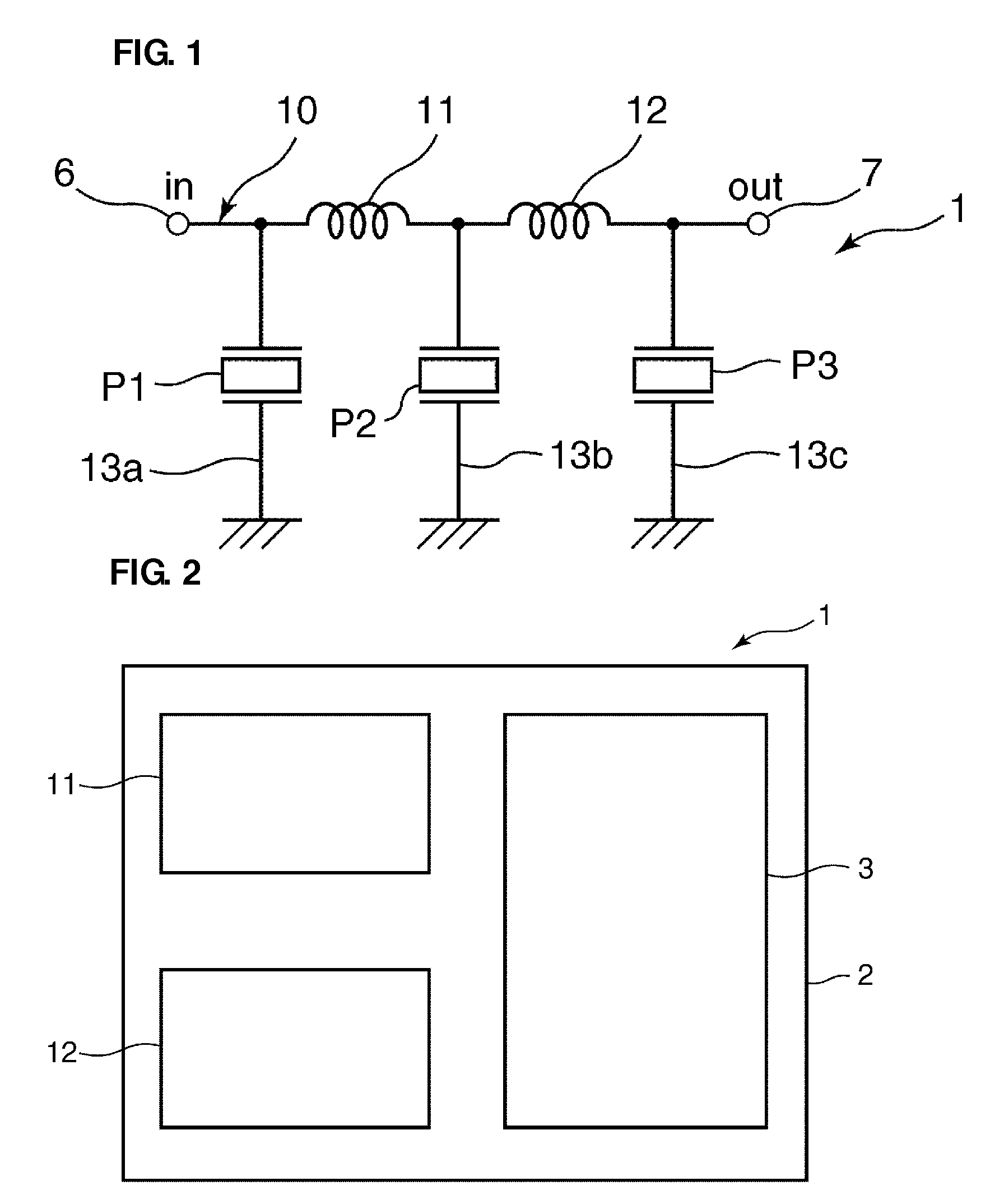
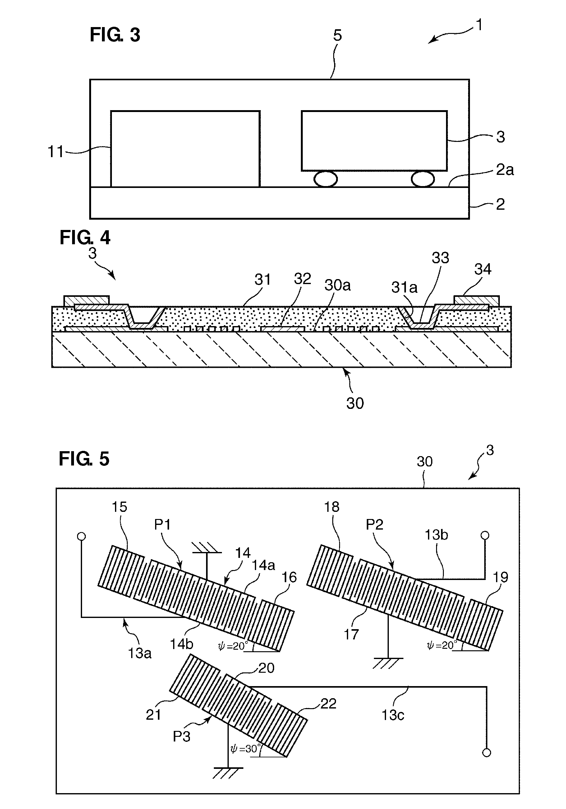
[0065]FIG. 1 is a circuit diagram illustrating a band rejection filter 1 according to a first preferred embodiment. FIG. 2 is a plan view schematically illustrating the band rejection filter 1. FIG. 3 is a sectional view schematically illustrating the band rejection filter 1. Note that, in FIG. 2, a lamination resin layer 5, which will be described hereinafter, is omitted.

[0066]As shown in FIG. 1, the band rejection filter 1 includes a ladder circuit including a series arm 10 which connects an input terminal 6 and an output terminal 7 to each other and first to third parallel arms 13a to 13c which are connected between the series arm 10 and the ground potential.

[0067]In the series arm 10, first and second inductance elements 11 and 12 are arranged. The first parallel arm 13a is connected between the ground potential and a point of connection between the input terminal 6 and the first inductance element 11. In the first parallel arm 13a, a first parallel arm resonator P1 is disposed....

second preferred embodiment

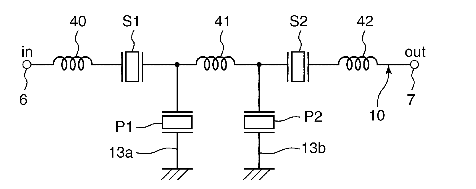
[0113]FIG. 8 is a circuit diagram illustrating a band rejection filter according to a second preferred embodiment. As shown in FIG. 8, the band rejection filter of the second preferred embodiment includes a ladder circuit including a series arm 10 which connects an input terminal 6 and an output terminal 7 to each other, and first and second parallel arms 13a and 13b which are connected between the series arm 10 and the ground potential. In the band rejection filter of the second preferred embodiment, first to third inductance elements 40 to and first and second series arm resonators S1 and S2 are arranged in the series arm 10. Specifically, the first and second series arm resonators S1 and S2 are connected to each other in series in the series arm 10. In the series arm 10, the first inductance element 40 is connected between the input terminal 6 and the first series arm resonator S1. The second inductance element 41 is connected between the first and second series arm resonators S1...

third preferred embodiment

[0142]FIG. 12 is a plan view schematically illustrating an elastic wave element according to a third preferred embodiment. As shown in FIG. 12, the band rejection filter according to the third preferred embodiment is preferably configured similarly to the band rejection filter according to the second preferred embodiment shown in FIG. 8 except for propagation angles (ψ) of first and second series arm resonators S1 and S2 and first and second parallel arm resonators P1 and P2.

[0143]Therefore, the band rejection filter according to the third preferred embodiment has first attenuation bands in which an insertion loss is large. The first attenuation bands are respectively formed on a lower side and a higher side. The lower first attenuation band is mainly formed by capacitances of the first and second series arm resonators S1 and S2. The higher first attenuation band is mainly formed by inductances of first to third inductance elements 40 to 42 and capacitances of the first and second p...


PUM


Abstract

An inexpensive compact band rejection filter realizes a high sharpness of a filter characteristic at ends of passbands and has a large attenuation. In the band rejection filter, at least one of a plurality of elastic wave resonators, which contributes to formation of a transition band, has a propagation angle larger than those of the other elastic wave resonators. Accordingly, the at least one of the plurality of elastic wave resonators which contributes to the formation of the transition band has an electromechanical coupling coefficient that is smaller than electromechanical coupling coefficients of the other elastic wave resonators.

Description

BACKGROUND OF THE INVENTION[0001]1. Field of the Invention[0002]The present invention relates to band rejection filters, and particularly relates to a band rejection filter having a ladder circuit configuration including a plurality of elastic wave resonators.[0003]2. Description of the Related Art[0004]In recent years, broadcasting service for mobile devices for digital terrestrial television broadcasting has been started in various countries including Japan, and practical use of such broadcasting service has been discussed in many countries. Under this circumstance, cellular phones having a function of receiving broadcasting service for mobile devices for digital terrestrial television broadcasting have been put into practical use. The cellular phones having the function of receiving broadcasting service for mobile devices for digital terrestrial television broadcasting include TV tuners used to receive the broadcasting service for mobile devices. In such a cellular phone, there a...

Claims


Application Information

Patent Timeline
IPC IPC(8): H03H9/64
CPCH03H9/14594H03H9/6409H03H9/6486H03H9/6483H03H2007/013
Inventor NAKAHASHI, NORIHIKOTANIGUCHI, YASUMASA
Owner MURATA MFG CO LTD
Why Eureka
Try Eureka