Composite image generating system, overlaying condition determining method, image processing apparatus, and image processing program

Active Publication Date: 2011-04-21
APPLE INC
View PDF26 Cites 124 Cited by
  • Summary
  • Abstract
  • Description
  • Claims
  • Application Information

AI Technical Summary

Benefits of technology

[0010]Further, in a case, where a marker might be a sellable item, like a playing card for playing AR-games, visible markers can easily be copied.
[0011]The present invention has been accomplished in consideration of the above problems, and it is an example of the object of the invention to provide a composit

Problems solved by technology

However, in a case where an image in which a marker is placed is image-captured, a marker which is originally unnecessary from the position of the viewer is naturally displayed in a captured image,

Method used


Image

  • Composite image generating system, overlaying condition determining method, image processing apparatus, and image processing program
  • Composite image generating system, overlaying condition determining method, image processing apparatus, and image processing program
  • Composite image generating system, overlaying condition determining method, image processing apparatus, and image processing program

Examples


first embodiment

1. First Embodiment

1.1 Outline of Structure and Function of AR System

[0037]First, an outline of the structure and function of the AR system S1 according to a first embodiment will be described with reference to FIG. 1.

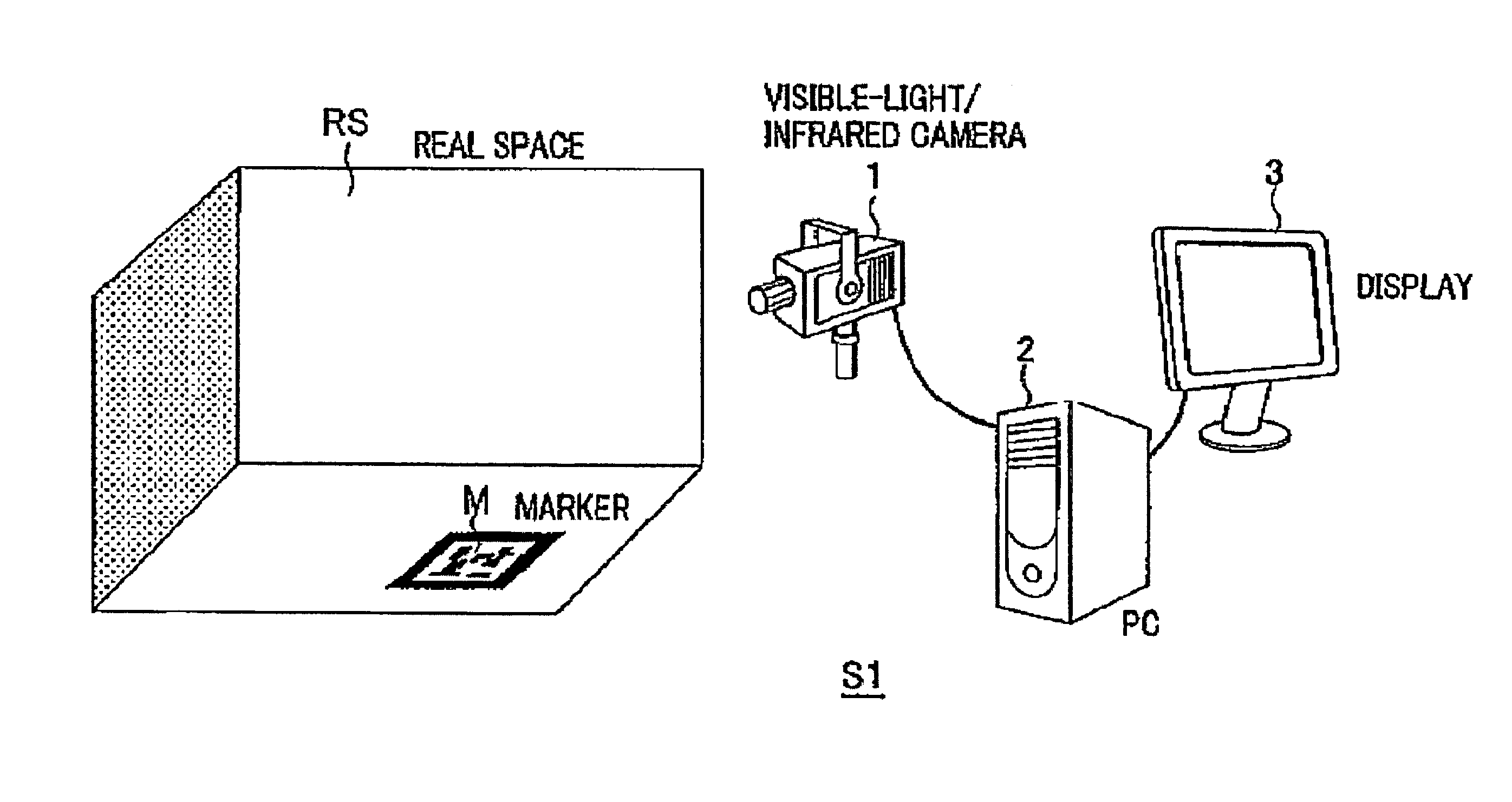
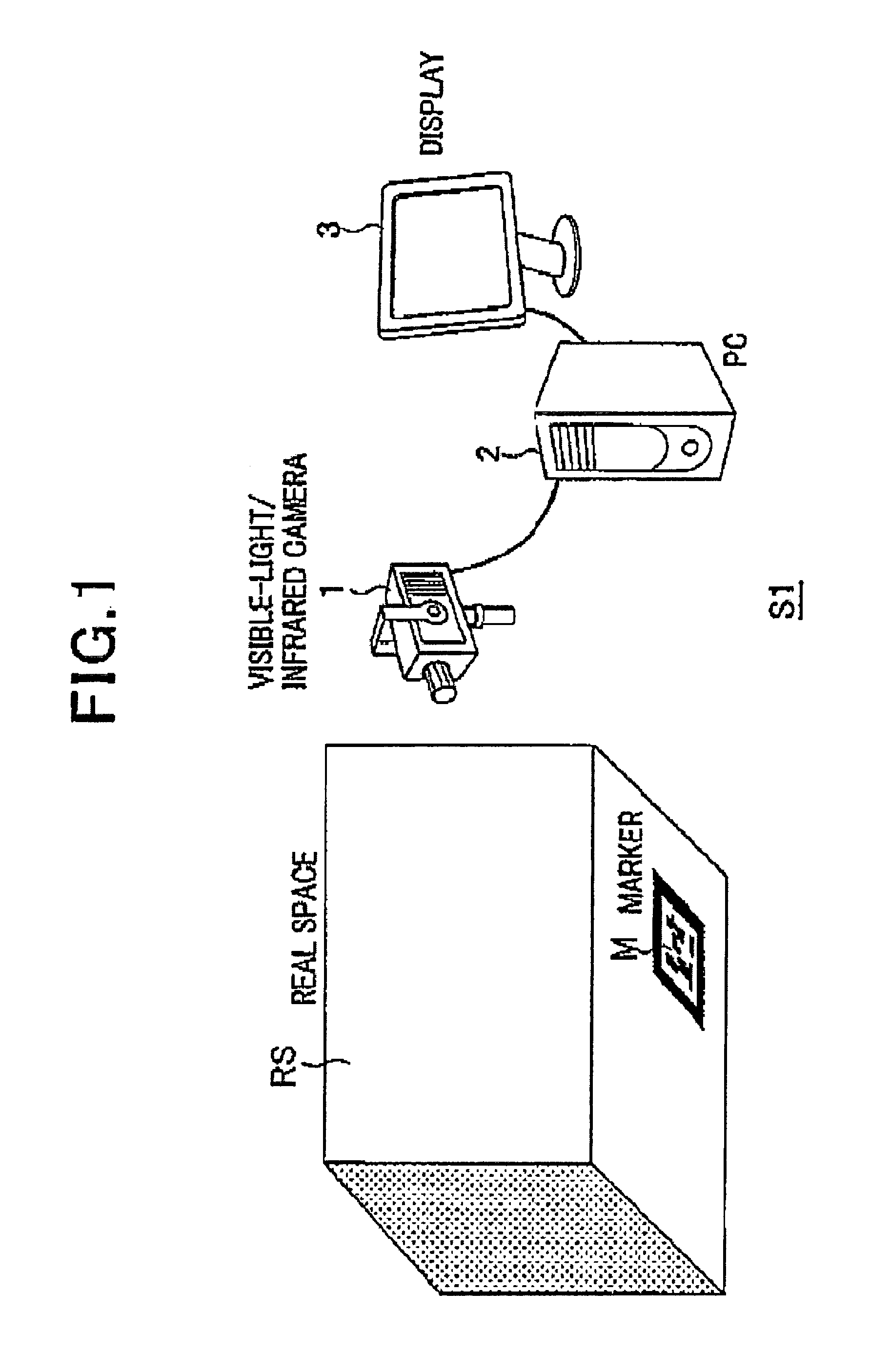
[0038]FIG. 1 is a view which shows an example of an outlined structure of the AR system S1 according to a first embodiment.

[0039]As shown in FIG. 1, an AR system S1 is arranged to include a visible-light / infrared camera 1 as an example of camera apparatus, a PC (Personal Computer) 2 as an example of image processing apparatus, and a display 3.

[0040]The visible-light / infrared camera 1 and the PC 2 are connected to each other by a video cable or the like. The PC 2 and the display 3 are connected to each other by a display cable or the like.

[0041]In the AR system S1 with such arrangement, as shown in FIG. 1, a marker M is located in a space RS which exists really, an image which includes the marker M is captured by the visible-light / infrared camera 1, and the PC 2 conduct...

second embodiment

2. Second Embodiment

[0087]Now, a second embodiment will be described. While a case in which a standard-camera is used is described in the first embodiment mentioned above, a special camera with the ability to capture not only one combined image, but to capture two images is to be used in the second embodiment. A standard camera means a camera which has a chip (or more than one chip) with photocells, which capture light in three or four different wavelengths of the visible spectrum (for example red, green, blue or red, green, blue, emerald), where also some non visible light is captured (if there is no IR-blocking filter). A special camera chip, for example comparable to the one published in US application 20070145273 (where in our case the transparent pixels could include a filter blocking visible light and the fourth pixel wavelength is used to create a separate image or a combined image, where IR-pixels are known to be at certain positions), and the according electronics, could be...


PUM


Abstract

A mark which at least reflects or radiates invisible light of predetermined wavelength other than visible light is added in a space of the real world. A camera apparatus comprises image capturing means for capturing a real image in which an invisible-light image may be discriminating. An image processing apparatus, comprises: mark discriminating means for discriminating at least one condition of a position of image of mark in the captured real image, a orientation of the mark, and a distance from the mark to the image capturing means, and overlaying condition determining means for determining, in correspondence with the discriminated condition, a overlaying condition which is at least one of an overlaying position which is a position of the image of the virtual object overlaid on the captured real image in the real image, an orientation of the virtual object which the age of the virtual object indicates, and a distance from a view point of viewer, of the image of the virtual object.

Description

[0001]This application is entitled to the benefit of, and incorporates by reference essential subject matter disclosed in PCT Application No. PCT / EP2009 / 002236 filed on Mar. 26, 2009, which claims priority to Japanese Patent Application No. 2008-082886 filed Mar. 27, 2008.BACKGROUND OF THE INVENTION[0002]1. Technical Field[0003]The present invention relates to the technical field of a composite image generating system, an overlaying condition determining method, an image processing apparatus, and an image processing program which overlays an image of at least one virtual object on an image of the real world, generating a composite image of the real world and the virtual object, and realizing augmented reality.[0004]2. Background Information[0005]A technique of overlaying an image of a virtual object on an image of the real world (or, an object which exists in a real space) to provide an image in which it looks as if the virtual object existed in the real world to augment a real worl...

Claims


Application Information

Patent Timeline
IPC IPC(8): H04N5/33G09G5/00H04N5/30
CPCG06T19/006G06T7/0044G06T7/74
Inventor ALT, THOMASMEIER, PETEROOKURA, MASAHIROEBLE, TOBIAS
Owner APPLE INC
Why Eureka
Try Eureka