Fiber shape sensing systems and methods

a fiber grating and sensing technology, applied in the field of fiber grating sensing systems and methods, can solve problems such as birefringence of fiber gratings

Active Publication Date: 2011-04-21
KONINKLIJKE PHILIPS ELECTRONICS NV +1
View PDF8 Cites 76 Cited by
  • Summary
  • Abstract
  • Description
  • Claims
  • Application Information

AI Technical Summary

Benefits of technology

[0005]Variations of fiber shape sensing or measuring systems, devices and methods are described herein. In certain variations, systems may be suitable for the measurement of bend, strain, roll and / or twist in localized areas where three or more fibers, e.g., optical fibers, are tapered and / or bonded. In certain embodiments, the optical fibers may be tapered and / or bonded by being heated and drawn down over a sensing area or region of interest where the draw down is optionally stopped before significant cross coupling can occur. This allows for the creation of a small shape sensing region over which three or more optical fibers are uniformly bonded together. Fiber gratings may be written into this region to support bend or twist measurements.

Problems solved by technology

In certain embodiments, a fiber grating may be written into at least one of the optical fibers in such a way that the writing process results in birefringence of the fiber grating.

Method used


Image

  • Fiber shape sensing systems and methods
  • Fiber shape sensing systems and methods
  • Fiber shape sensing systems and methods

Examples


Embodiment Construction

[0058]Variations of the devices are best understood from the detailed description when read in conjunction with the accompanying drawings. It is emphasized that, according to common practice, the various features of the drawings may not be to-scale. On the contrary, the dimensions of the various features may be arbitrarily expanded or reduced for clarity. The drawings are taken for illustrative purposes only and are not intended to define or limit the scope of the claims to that which is shown.

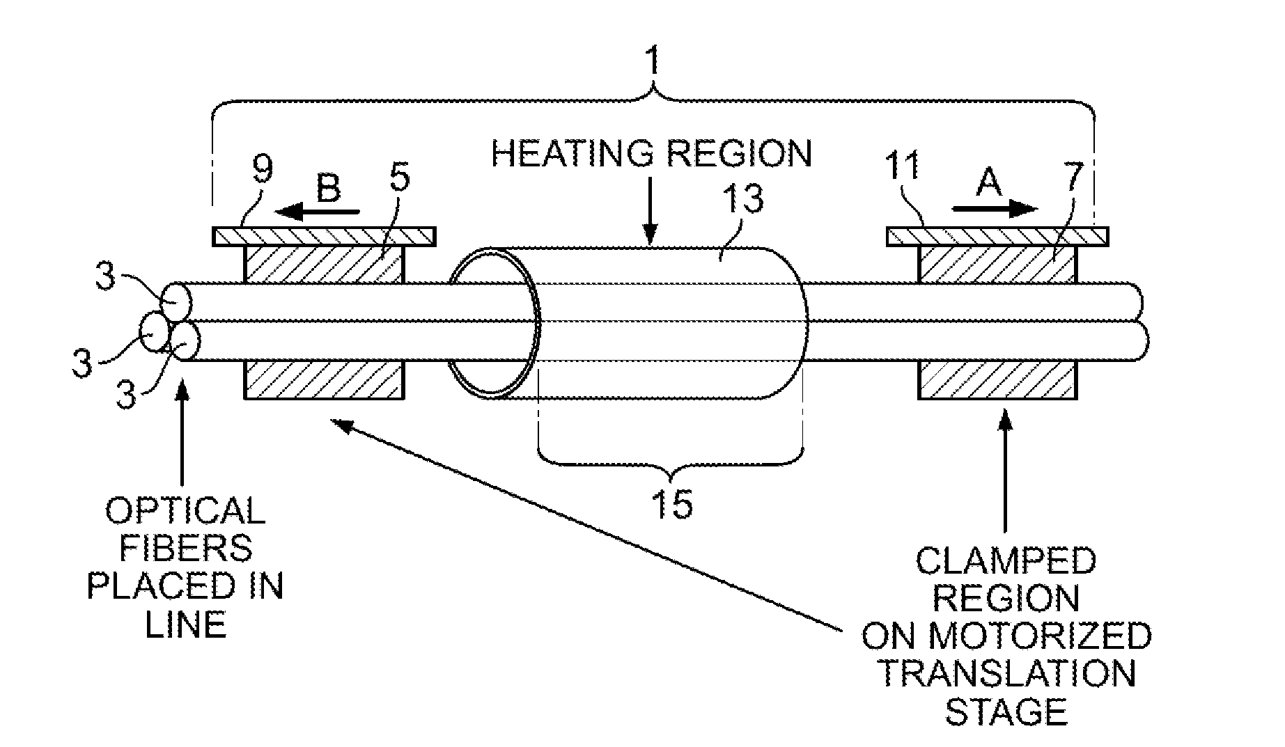
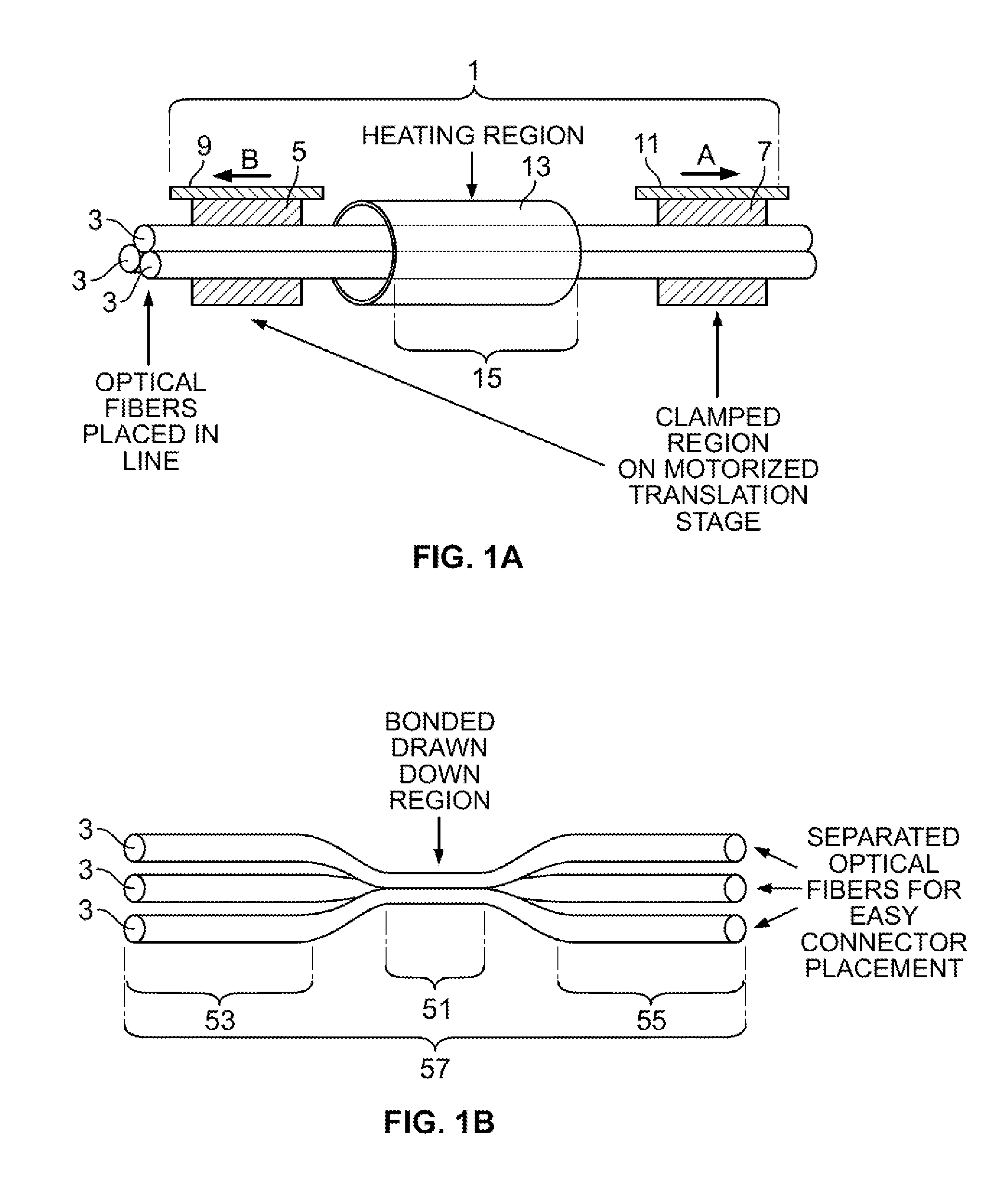
[0059]FIG. 1B illustrates one variation of a shape sensing or measuring system 57 having three aligned fibers, e.g., optical fibers 3. The system includes a combined, adhered, fused or bonded region 51. The system may also include end regions 53 and 55 where the optical fibers 3 are mechanically independent and may be easily interfaced to connectors or spliced. In certain variations, the bonded region 51 may be designed such that when light is coupled into any one of the optical fibers 3 there...


PUM

PropertyMeasurementUnit
diameteraaaaaaaaaa
angleaaaaaaaaaa
angleaaaaaaaaaa

Abstract

In certain variations, fiber shape sensing or measuring systems, devices and methods are described herein, which allow for measurement of three dimensional bending as well as twist measurements of various fibers, e.g., optical fibers and fiber optic probes of various sizes. In certain variations, the systems are designed to take advantage of unique light guiding properties of optical fibers and various fiber gratings.

Description

CROSS-REFERENCE TO RELATED APPLICATION[0001]This application claims the benefit of priority to U.S. Prov. Pat. App. 61 / 225,883 filed Jul. 15, 2009, which is incorporated herein by reference in its entirety.BACKGROUND[0002]Earlier efforts have demonstrated that three independent fiber lines containing multiplexed fiber gratings can be used to support shape sensing. This has been done by using three independent optical fibers in systems similar to those described by Chen, Bucholtz and others. Systems utilizing three independent fibers, in some instances, may by subject to the effects of spatial placement and relative motion between the optical fibers.[0003]Multi-core optical fibers have also been utilized in certain systems. Multi-core optical fibers, however, may be subject to the need to break out the cores of the optical fibers for interfacing to read out units, and existing procedures for breaking out the fiber cores can be costly.[0004]Thus, there is a need for improved systems u...

Claims


Application Information

Patent Timeline
Patent Type & Authority Applications(United States)
IPC IPC(8): G01N21/00
CPCA61B19/0248A61B19/5244G01D5/35383A61B2019/5261G01B11/18A61B2019/0255A61B34/20A61B50/10A61B50/15A61B2034/2061G01D5/35316G01D5/35387A61B1/009
Inventor UDD, ERIC
Owner KONINKLIJKE PHILIPS ELECTRONICS NV
Why Eureka
Try Eureka