Cross Groove Type Constant Velocity Joint

a constant velocity joint and cross-grain technology, applied in the direction of yielding couplings, shafts for rotary movement, couplings, etc., can solve the problems of deteriorating the load bearing capacity of the joint, and achieve the effect of compact and durable structure and enhanced strength of the cage web

Active Publication Date: 2011-04-21
HYUNDAI WIA
View PDF28 Cites 2 Cited by
  • Summary
  • Abstract
  • Description
  • Claims
  • Application Information

AI Technical Summary

Benefits of technology

[0009]In order to solve the above described and other shortcomings or drawbacks known in the conventional cross groove joints, the present invention provides a cross groove joint (preferably, but not necessarily, of higher ball type) with a compact and durable structure, in particular, with the strength of the cage web enhanced than that of the conventional cross groove joints as described above.

Problems solved by technology

Therefore, the higher ball (e.g., eight ball) type cross groove joint may have a weakened strength and durability in the cage web, and thus, the load bearing capacity of the joint can be deteriorated than that of the conventional six ball type joint.

Method used


Image

  • Cross Groove Type Constant Velocity Joint
  • Cross Groove Type Constant Velocity Joint
  • Cross Groove Type Constant Velocity Joint

Examples


Embodiment Construction

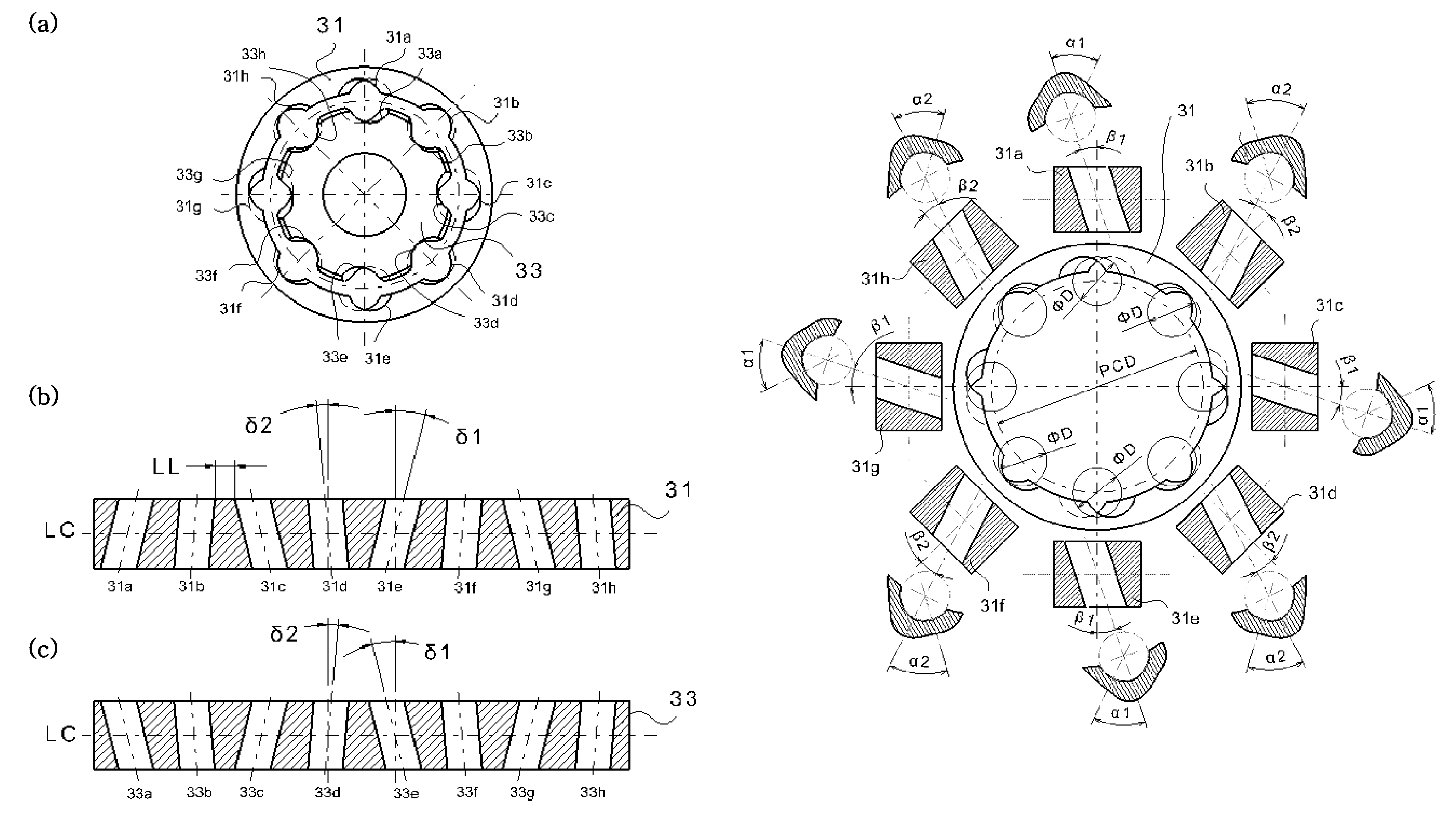
[0049]The present invention will be explained and illustrated below in association with several embodiments to be described later, in particular, the cross groove joint of eight ball type. However, it is noted that the present invention is not limited to the eight ball type joint, but is applicable to the cross groove joint of any ball type, for example, having six, eight, ten, or more balls.

[0050]Referring to FIGS. 5-11 of the drawings, the cross groove type constant velocity joints of the present invention are described herein in details in association with several exemplary or preferred embodiments thereof. However, the following descriptions of such embodiments are intended primarily for illustrating the principles and exemplary constructions of the constant velocity joints of the present invention, and the present invention is not specifically limited to these exemplary embodiments. Thus, one skilled in the art can appreciate or recognize that various modifications and substitu...


PUM


Abstract

A constant velocity joint for a drive system comprises: an outer joint member having a plurality of inwardly facing outer ball grooves, the outer ball grooves consisting of a first group of grooves, each groove of which having a skewed groove shape with a first skew angle other than zero and alternately arranged in opposite directions relative to an axis of rotation of outer joint member, and a second group of grooves, each groove of which having a skewed groove shape with a second skew angle other than zero and alternately arranged in opposite directions relative to an axis of rotation of outer joint member, the second skew angle less than the first skew angle; and an inner joint member disposed inside the outer joint member and having a plurality of outwardly facing inner ball grooves consisting of a first group of grooves, each groove of which having a skewed groove shape with a first skew angle other than zero and alternately arranged in opposite directions relative to an axis of rotation of inner joint member, and a second group of grooves, each groove of which having a skewed groove shape with a second skew angle other than zero and alternately arranged in opposite directions relative to an axis of rotation of inner joint member, the second skew angle less than the first skew angle, each inner ball groove of the inner joint member being coupled with a corresponding outer ball groove of the outer joint member generally in crossed pair. In addition to the differentiated skew angles, the contact angles of the balls in the first and second group of grooves and other configurations may also be differentiated.

Description

FIELD OF THE INVENTION[0001]The present invention relates to a cross groove type constant velocity joint for use in a drive system, and more particularly, to a cross groove type constant velocity joint having composite groove shapes, typically for use in a drive system of, for example, an automobile for transmitting rotational torque between two rotating shafts thereof.BACKGROUND OF THE INVENTION[0002]A cross groove type constant velocity joint (hereinafter to be referred as a “cross groove joint”) is one type of constant velocity universal joints used for transmitting rotational torque between the rotating shafts (i.e., the driving shaft and the driven shaft), typically for the drive system of automobiles. The cross groove joint includes an outer joint member with a plurality of ball grooves formed on the inner surface thereof, and an inner joint member with a plurality of ball grooves formed on the outer surface thereof, in which the corresponding ball grooves of the outer joint m...

Claims


Application Information

Patent Timeline
Patent Type & Authority Applications(United States)
IPC IPC(8): F16D3/224
CPCF16C1/04F16D3/227
Inventor OH, SEUNG TARKKIM, TAE HONG
Owner HYUNDAI WIA
Why Eureka
Try Eureka