Fluid Delivery System, Fluid Path Set, and Pressure Isolation Mechanism with Hemodynamic Pressure Dampening Correction
What is Al technical title?
Al technical title is built by PatSnap Al team. It summarizes the technical point description of the patent document.
a delivery system and fluid path technology, applied in the field of fluid delivery systems, can solve the problems of requiring operator effort, reducing the efficiency of the injection tube,
Active Publication Date: 2011-04-21
BAYER HEALTHCARE LLC
View PDF99 Cites 86 Cited by
Summary
Abstract
Description
Claims
Application Information
AI Technical Summary
This helps you quickly interpret patents by identifying the three key elements:
Problems solved by technology
Method used
Benefits of technology
[0021]In one aspect, the manual control includes a first actuator providing control of flow rate of the first fluid by changing the force on the first actuator and a second actuator, the second actuator causing the injector to enter into a preprogrammed high pressure injection mode when placed in an on state. The system may further include a pressure sensor in fluid communication with the second fluid path via a pressure-activated isolator that isolates the pressure sensor from pressures in the second fluid path above a set pressure. In one embodiment, the per-patient disposable section may include a check valve in the second fluid path separating components of the per-patient disposable section from the multi-patient reusable section to reduce or eliminate flow of contaminated fluid into the multi-patient reusable section.
[0079]The first annular member may be adapted to coaxially receive the second annular member. The first annular member may be internally threaded and the second annular member may be externally threaded such that first and second annular members threadably engage to securely and releasably connect the first and second connector members. One of the first and second luer members may be formed as a male luer and the other may be formed as a female luer. The first annular member and first luer member may define an annular cavity therebetween such that the second annular member is at least partially received in the annular cavity when the first and second annular members are in operative engagement. When the second annular member is at least partially received in the annular cavity, the annular cavity may form a liquid-trapping chamber for inhibiting leakage of liquid between the first and second connector members.
Problems solved by technology
Manual sources of fluid pressure and flow used in medical applications such as syringes and manifolds thus typically require operator effort that provides feedback of the fluid pressure / flow generated to the operator.
The feedback is desirable, but the operator effort often leads to fatigue.
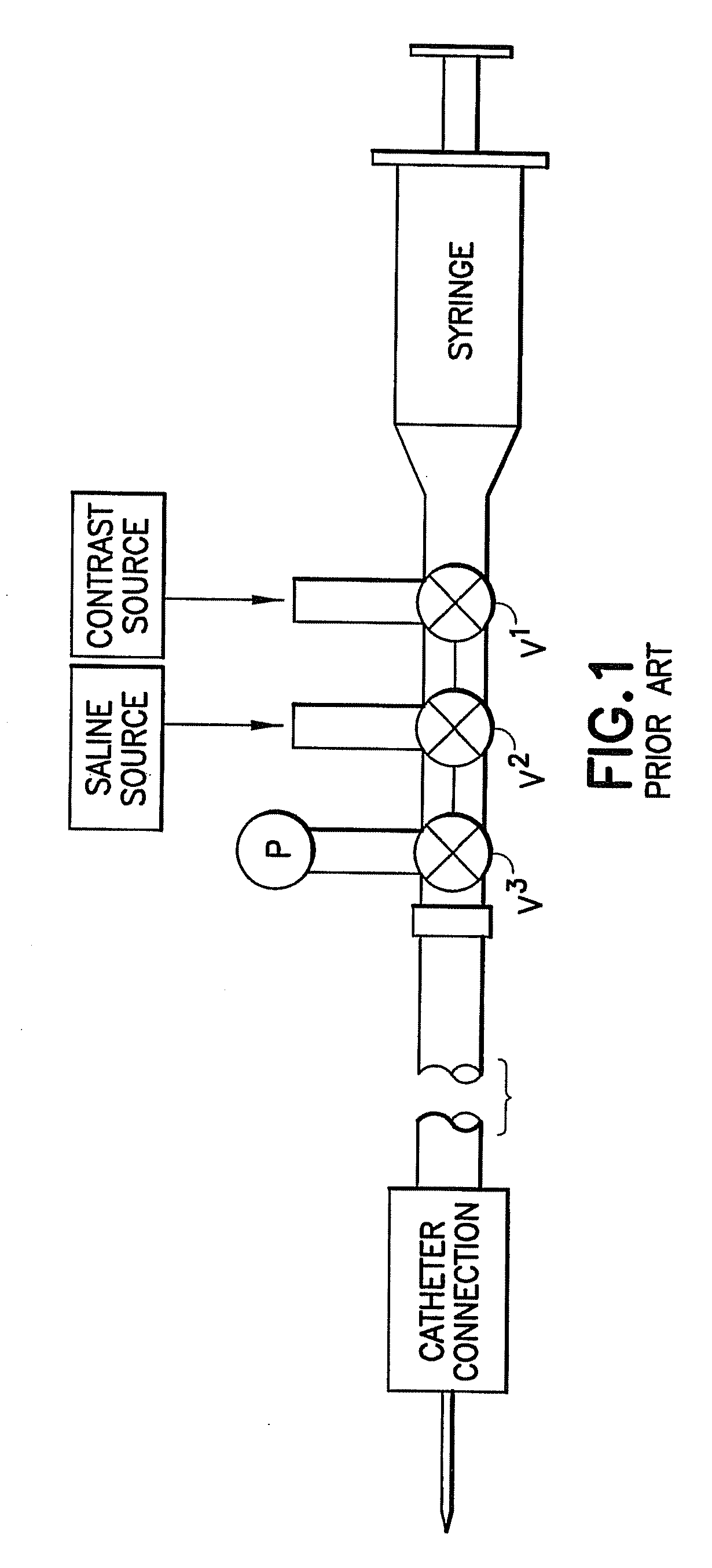
However, compliance in the system components, for example, expansion of the syringe, tubing, and other components under pressure, using such a manifold system can lead to a less than optimal injection bolus.
Moreover, the arrangement of the system components of U.S. Pat. No. 5,800,397 results in relatively large amounts of wasted contrast and / or undesirable injection of an excessive amount of contrast when the low pressure, typical saline system, is used.
Unlike manual injection systems, however, there is little if any feedback to the operator of system pressure in the systems disclosed in the U.S. patents identified previously.
Method used
Image
Click on the blue label to locate the original text in one second.
Reading with bidirectional positioning of images and text.
Examples
Embodiment Construction
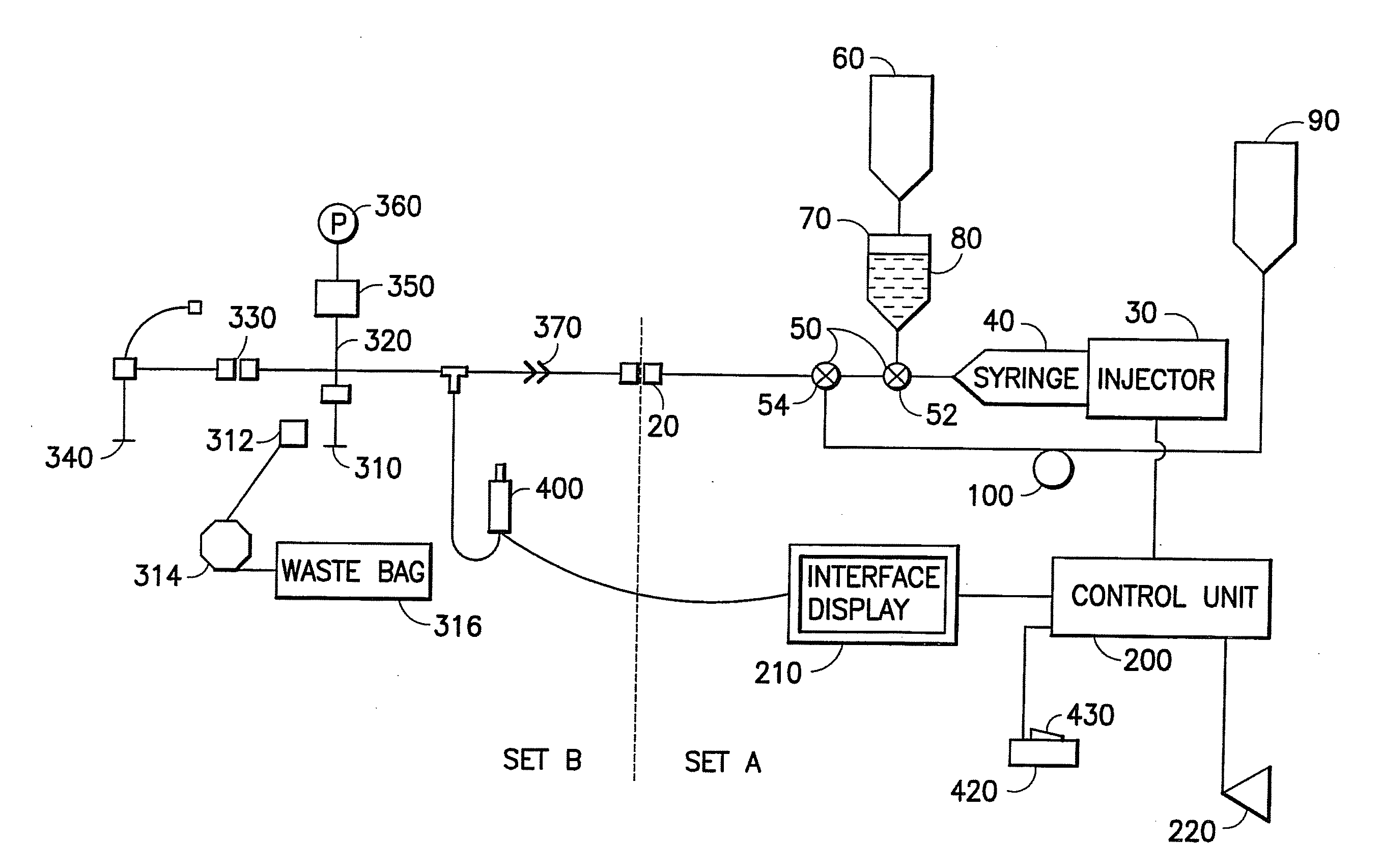
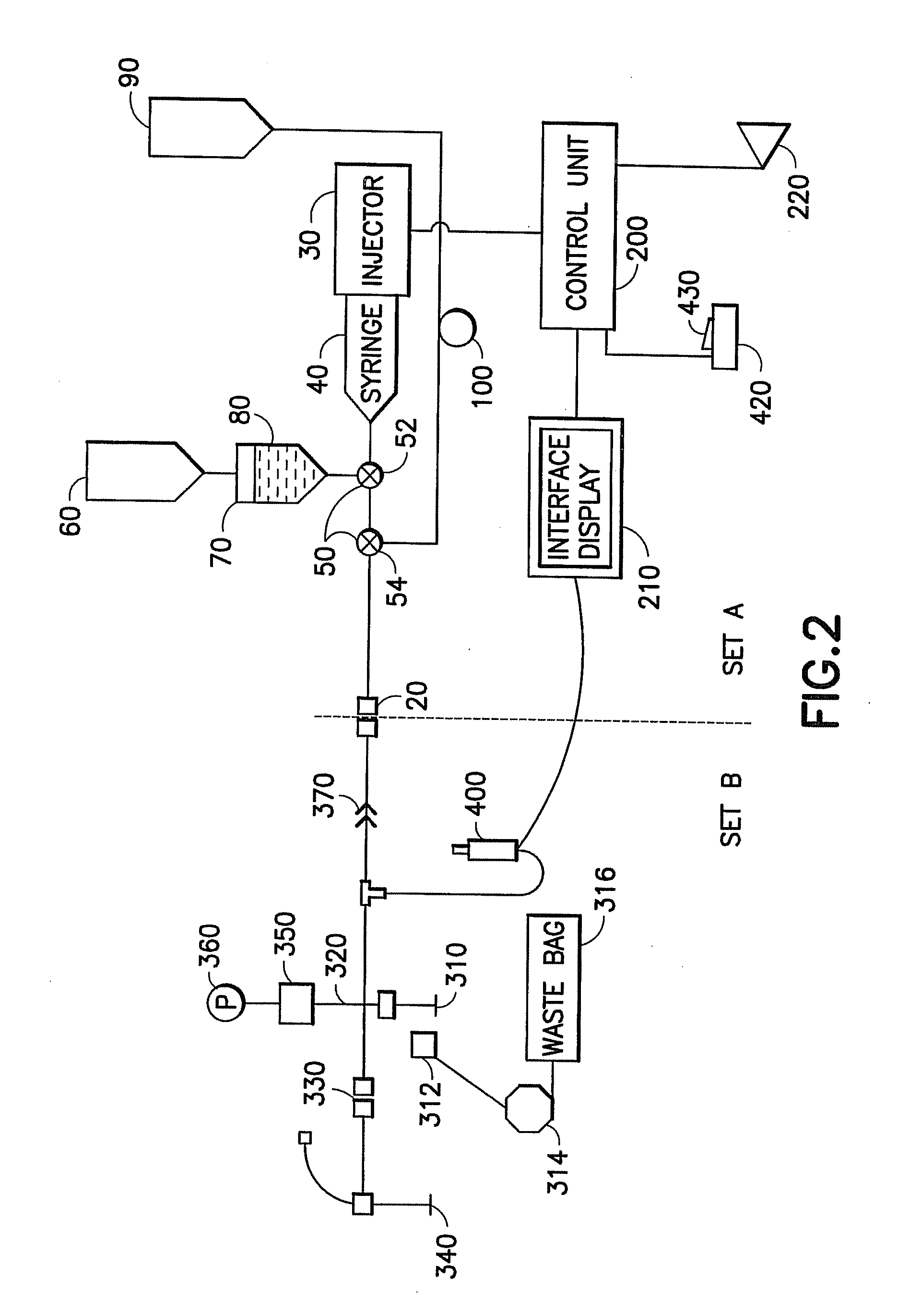
[0155]In one aspect, the present invention provides an energy / signal source to generate fluid pressure / flow while also providing to the user tactile and / or audible feedback of the fluid pressure generated, allowing the user to modulate the fluid pressure / flow. The powered injection system of the present invention is capable of providing, for example, both precise low-flow / low-pressure fluid delivery for powered coronary injections and high-flow / high-pressure fluid delivery for ventricle injections.
[0156]FIG. 2 illustrates one embodiment of the present invention in which injector system 10 is preferably divided into two sections: a multi-patient section or set A and a per-patient disposable section or set B. Section or set A and section or set B are preferably separated and removably coupled into fluid connection by a high-pressure connector or by a high-pressure, “aseptic” connector 20 such as the septum connector disclosed in U.S. Pat. No. 6,096,011, assigned to the assignee of the...
PUM
Abstract
The fluid delivery system includes a pressurizing device for delivering injection fluid under pressure, a low pressure fluid delivery system, and a pressure isolation mechanism. The pressure isolation mechanism includes a first lumen associated with the pressurizing device, a second lumen associated with the low pressure fluid delivery system, and a pressure isolation port. The first valve is in a normally open position permitting fluid communication between the first lumen and the second lumen and movable to a closed position when fluid pressure in the first lumen reaches a predetermined pressure level. The first valve isolates the pressure isolation port from the first lumen in the closed position. A second valve is associated with the second lumen and regulates fluid flow through the second lumen. The second valve may be a disk valve defining one or more passageways in the form of slits through the body of the disk valve.
Description
CROSS-REFERENCE TO RELATED APPLICATIONS[0001]This application is division of application Ser. No. 11 / 551,027, filed on Oct. 19, 2006, now abandoned, which is a continuation-in-part of application Ser. No. 11 / 004,670, filed on Dec. 3, 2004, which is a continuation-in-part of application Ser. No. 10 / 826,149, filed on Apr. 16, 2004, now U.S. Pat. No. 7,611,503, the disclosures of which are incorporated herein by reference.RELATED APPLICATIONS[0002]This application may contain subject matter that is related to that disclosed in the following applications: (1) application Ser. No. 10 / 818,748, filed on Apr. 6, 2004, now U.S. Pat. No. 7,326,186; (2) application Ser. No. 10 / 818,477, filed on Apr. 5, 2004, now U.S. Pat. No. 7,563,249; (3) application Ser. No. 10 / 326,582, filed on Dec. 20, 2002, now U.S. Pat. No. 7,549,977; (4) application Ser. No. 10 / 237,139, filed on Sep. 6, 2002, now U.S. Pat. No. 6,866,654; and (5) application Ser. No. 09 / 982,518, filed on Oct. 18, 2001, now U.S. Pat. No....
Claims
Application Information
Patent Timeline
Application Date:The date an application was filed.
Publication Date:The date a patent or application was officially published.
First Publication Date:The earliest publication date of a patent with the same application number.
Issue Date:Publication date of the patent grant document.
PCT Entry Date:The Entry date of PCT National Phase.
Estimated Expiry Date:The statutory expiry date of a patent right according to the Patent Law, and it is the longest term of protection that the patent right can achieve without the termination of the patent right due to other reasons(Term extension factor has been taken into account ).
Invalid Date:Actual expiry date is based on effective date or publication date of legal transaction data of invalid patent.
Patent Type & Authority Applications(United States)