Adiabatic compressed air energy storage system with combustor

Inactive Publication Date: 2011-04-28
GENERAL ELECTRIC CO
View PDF17 Cites 36 Cited by
  • Summary
  • Abstract
  • Description
  • Claims
  • Application Information

AI Technical Summary

Benefits of technology

[0013]In accordance with one aspect of the invention, an air compression and expansion system includes a drive shaft, a motor-generator coupled to the drive shaft, a compressor coupled to the drive shaft and configured to output compressed air to a cavern via a first line, and a turbine coupled to the drive shaft and configured to receive air from the cavern via a second line. The system includes a first thermal energy storage (TES) device having the first line and the second line thermally coupled thereto, a combustor thermally coupled to the second line, the combustor con

Problems solved by technology

However, above-ground systems tend to be expensive and typically do not have a storage capacity comparable to an underground cavern—though they can be attractive in that they can be sited in areas where underground formations are not available.
However, although the heat of compression may be present when entering the cavern, its energetic value is largely diminished as it mixes with cavern air, and as it further cools to surrounding or ambient temperature during storage.
Thus, diabatic-CAES systems do not store the heat of compression, and the availability due thereto is lost—leading to a low overall efficiency.
However, despite a multi-stage operation, an adiabatic operation of an ACAES, and a corresponding efficiency improvement thereof over a diabatic system, ACAES systems nevertheless lose energy due to other thermodynamic limitations, such as friction in the turbines and other second-law effects.
Thus, because of the inherent thermodynamic limitations, ACAES systems take more energy from an electrical grid than they provide back to the grid during power generation from storage.
As such and despite charging during low-cost / low-demand periods and drawing during high-profit peak capacity periods, their operation is limited, and profitability may be compromised due to the lost power.
However, in instances where the air storage cavern or the TES is depleted, it is possible that peak power demands from the electrical grid may not be met by using the air storage system.
In other words, an air storage system typically provides additional power generation capability from a turbine / generator combination, but power may not be available therefrom during the times when it is needed most—during peak power demand.

Method used


Image

  • Adiabatic compressed air energy storage system with combustor
  • Adiabatic compressed air energy storage system with combustor
  • Adiabatic compressed air energy storage system with combustor

Examples


Embodiment Construction

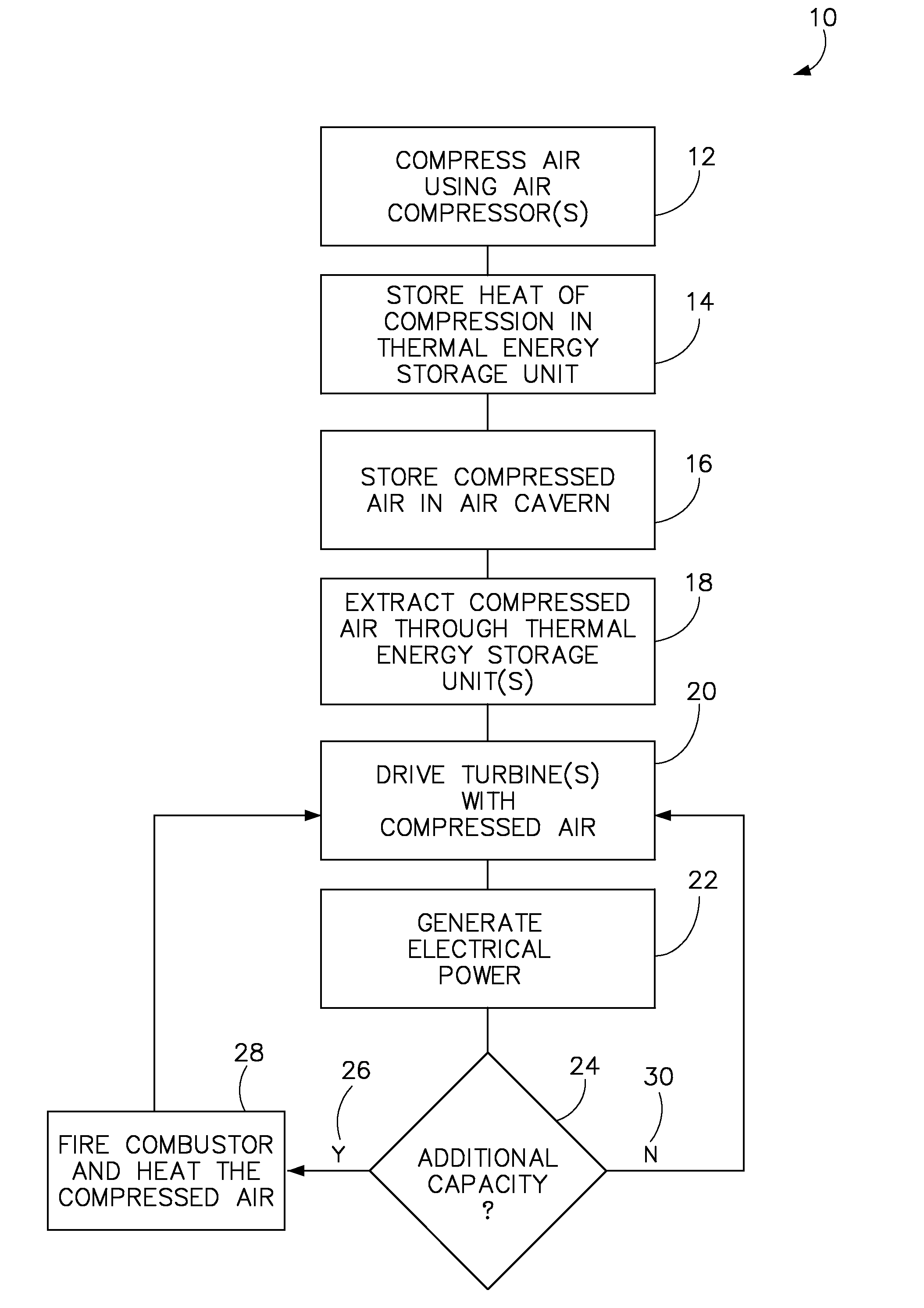
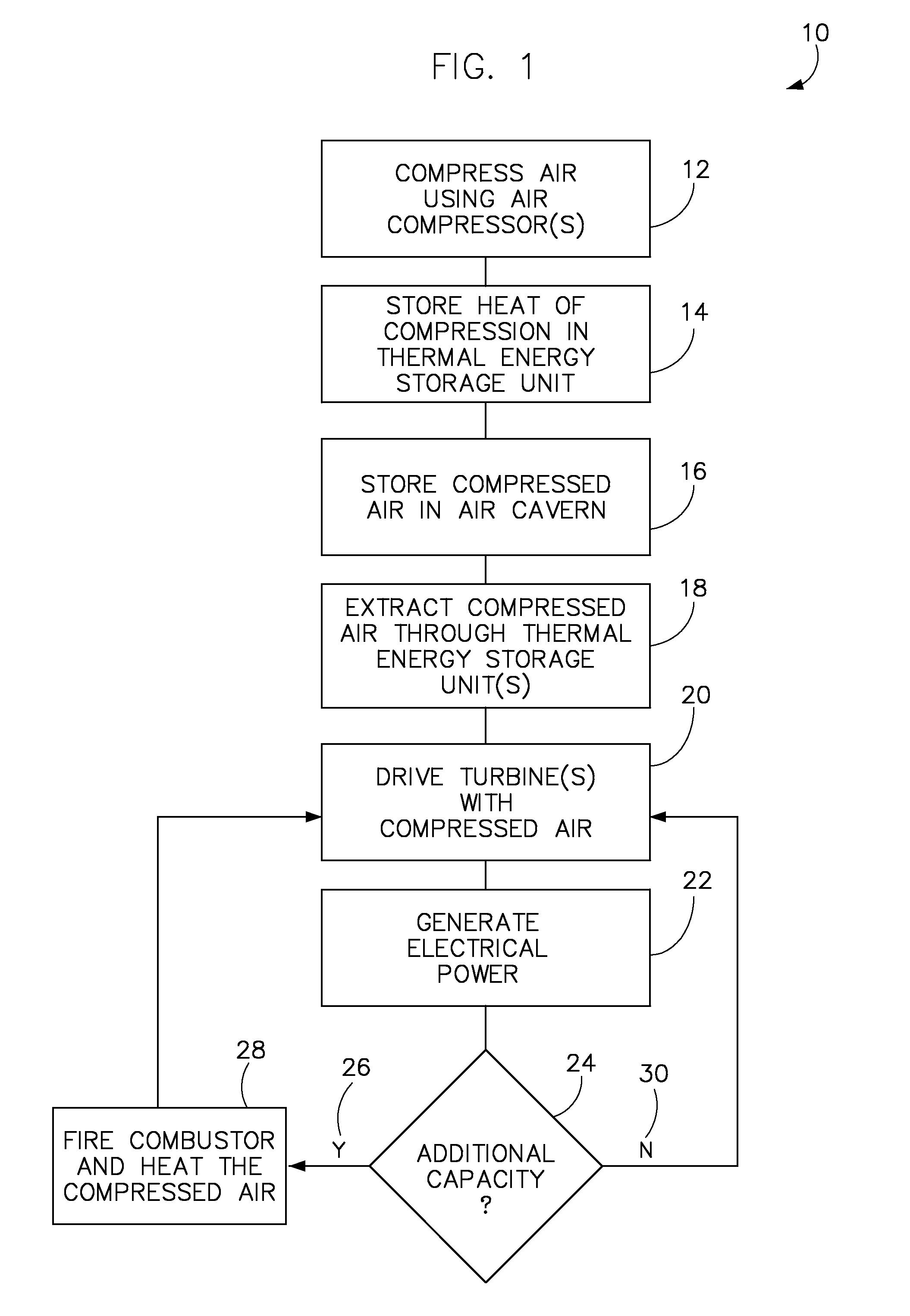
[0022]According to embodiments of the invention, a system and method are provided that optionally augment an energy content of air passing from a pressurized air cavern to a turbine to generate electrical power therefrom.

[0023]Referring to FIG. 1, a technique 10 for operating a compressed air storage system includes compressing a working fluid such as air using one or more air compressors 12, storing the heat of compression in one or more thermal energy storage units (TES) 14, and storing the compressed air in an air cavern 16, according to embodiments of the invention. Energy is thus stored in one or more TES units as thermal energy that is available for later extraction via heat exchange with air passing therethrough. Air is extracted therefrom 18 through the one or more TES units, and one or more turbines is driven 20 with the compressed air. The turbine(s), in turn, generate electrical power 22 via, for instance, an electrical generator.

[0024]Technique 10 includes determining 24...


PUM


Abstract

A system includes a drive shaft, a motor-generator coupled to the drive shaft, a compressor coupled to the drive shaft and configured to output compressed air to a cavern, and a turbine coupled to the drive shaft and configured to receive air from the cavern. The system includes a first thermal energy storage (TES) device, a combustor configured to combust a flammable substance and generate an exhaust stream to the turbine, and controller. The controller is configured to control flow of the air to heat the air as it passes through the first TES, cause the flammable substance to flow to the combustor, operate the combustor to combust the air with the flammable substance to generate an exhaust stream into the turbine, and control the motor-generator to generate electrical energy from energy imparted thereto from the turbine via the drive shaft.

Description

BACKGROUND OF THE INVENTION[0001]Embodiments of the invention generally relate to compressed air energy storage systems and, more particularly, to a system and method of maximizing power output and efficiency in an adiabatic air energy storage system.[0002]Compressed air energy storage systems include diabatic compressed air energy storage (diabatic-CAES) and adiabatic compressed air energy storage (ACAES). Such systems typically store compressed air to 80 bars or more, where the energy stored is available to later power a turbine to generate electricity. Typically, the compressed air can be stored in several types of underground media that include but are not limited to porous rock formations, depleted natural gas / oil fields, and caverns in salt or rock formations. In one example, a man-made solution-mined salt cavern of approximately 19.6 million cubic feet operates between 680 psi and 1280 psi, and is capable of providing power for a continuous time duration of 26 hours. Alternat...

Claims


Application Information

Patent Timeline
IPC IPC(8): F02C6/16F02C6/14F02C7/08F02C7/10F02C9/00
CPCF02C6/14F02C6/16F05D2260/20Y02E60/15F02C9/50Y02E60/16
Inventor FREUND, SEBASTIAN W.FINKENRATH, MATHIAS
Owner GENERAL ELECTRIC CO
Why Eureka
Try Eureka