Moisture separation system and method of assembling the same

a technology of moisture separator and air filtration system, which is applied in the direction of separation process, liquid degasification, combustion air/fuel air treatment, etc., can solve the problems of increasing the overall pressure loss of the gas turbine air filtration system, clogging the moisture separator, etc., to facilitate the removal of moisture from the airflow

Inactive Publication Date: 2011-04-28
BHA ALTAIR
View PDF18 Cites 8 Cited by
  • Summary
  • Abstract
  • Description
  • Claims
  • Application Information

AI Technical Summary

Benefits of technology

[0004]In one aspect, a method of assembling a moisture separation system for a gas turbine power system is provided. The gas turbine power system includes a filter housing assembly and a weather hood coupled to the filter housing assembly, and the weather hood defines an inlet for directing airflow into the filter housing assembly. The method includes providing a moisture separator and coupling the moisture separator to the weather hood such that the moisture separator extends at least partially across the inlet, the moisture separator rotatable in response to the airflow to facilitate removing moisture from the airflow.
[0005]In another aspect, a moisture separation system for a gas turbine power system that includes a filter housing assembly is provided. The moisture separation system includes a weather hood configured to be coupled to the filter housing assembly, the weather hood defining an inlet for directing airflow into the filter housing assembly. The moisture separation system also includes a moisture separator configured to be coupled to the weather hood such that the moisture separator extends at least partially across the inlet and such that the moisture separator is rotatable in response to the airflow to facilitate removing moisture from the airflow.

Problems solved by technology

During the drier periods, air carries dust through the channels without substantial amounts of moisture, thereby facilitating a build-up of dust on the walls of the moisture separator, which can clog the moisture separator and increase overall pressure loss within the gas turbine air filtration system.

Method used


Image

  • Moisture separation system and method of assembling the same
  • Moisture separation system and method of assembling the same
  • Moisture separation system and method of assembling the same

Examples


Embodiment Construction

[0012]The following detailed description illustrates a moisture separation system and a method of assembling the same by way of example and not by way of limitation. The description enables one of ordinary skill in the art to make and use the disclosure, and the description describes several embodiments of the disclosure, including what is presently believed to be the best mode of carrying out the disclosure. The disclosure is described herein as being applied to a preferred embodiment, namely, a gas turbine power system. However, it is contemplated that this disclosure has general application to moisture separation in a broad range of systems and in a variety of applications other than gas turbine power systems.

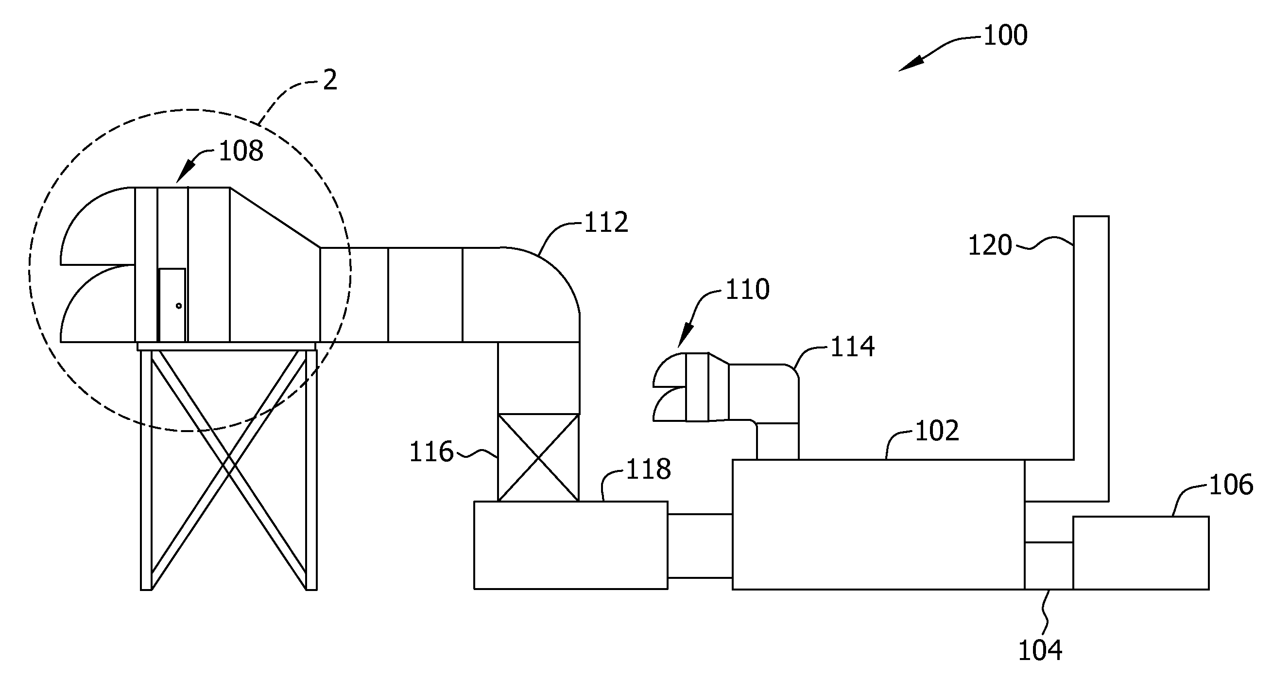
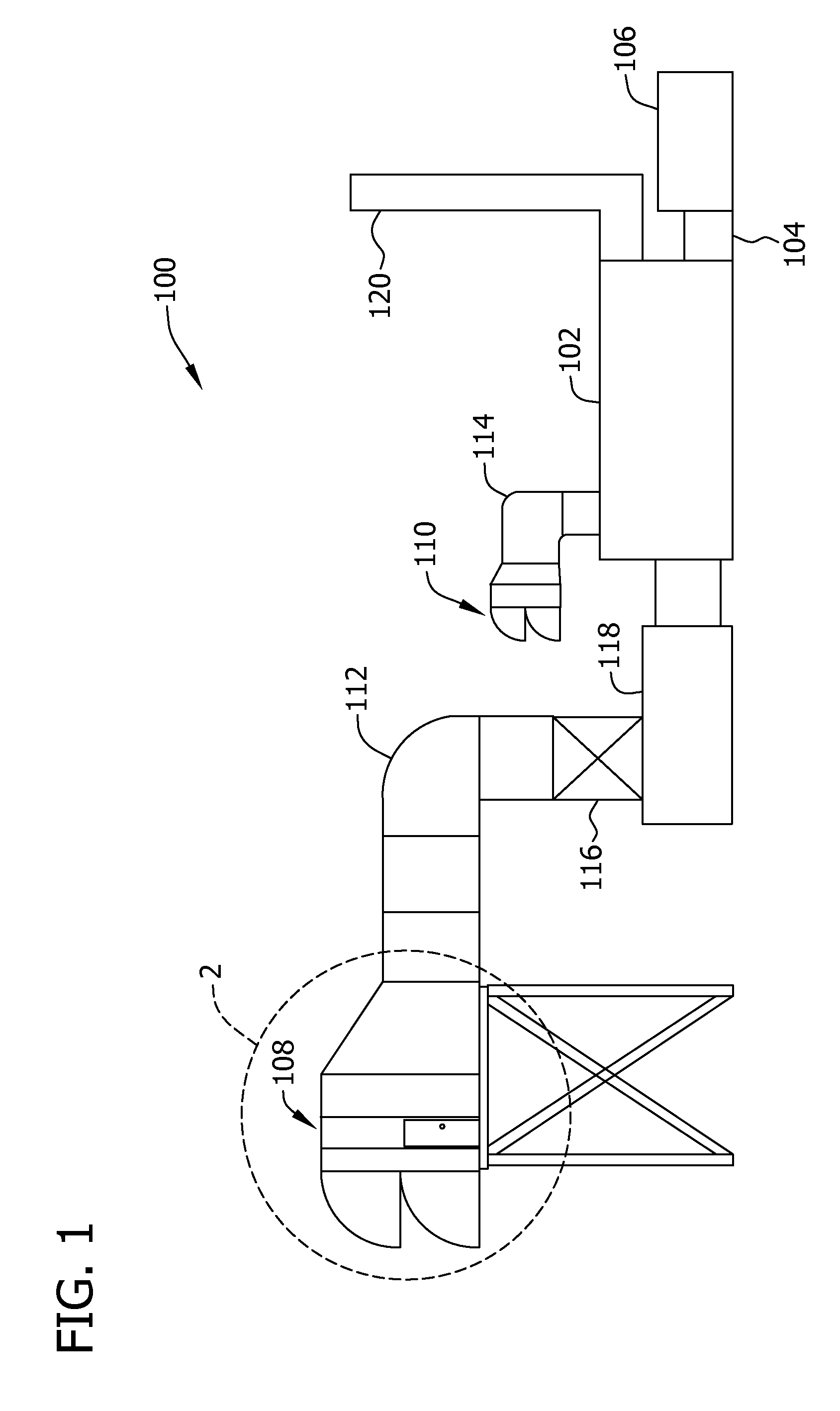
[0013]FIG. 1 illustrates an exemplary gas turbine power system 100. In the exemplary embodiment, gas turbine power system 100 includes a gas turbine housed within a gas turbine housing 102, a gear assembly housed within a gear housing 104, and a generator housed within a gen...


PUM

PropertyMeasurementUnit
humidityaaaaaaaaaa
pressure lossaaaaaaaaaa
dimension FDaaaaaaaaaa

Abstract

A method of assembling a moisture separation system for a gas turbine power system is provided. The gas turbine power system includes a filter housing assembly and a weather hood coupled to the filter housing assembly, and the weather hood defines an inlet for directing airflow into the filter housing assembly. The method includes providing a moisture separator and coupling the moisture separator to the weather hood such that the moisture separator extends at least partially across the inlet, the moisture separator rotatable in response to the airflow to facilitate removing moisture from the airflow.

Description

BACKGROUND OF THE INVENTION[0001]The field of this disclosure relates generally to moisture separators and, more particularly, to a moisture separator for a gas turbine air filtration system.[0002]Many known gas turbine power systems include filters and moisture separators that facilitate removing moisture and debris from the air before the air is drawn into the compressor of the gas turbine. Specifically, at least some known moisture separators direct air through a series of non-linear channels such that the inertia of the moisture in the air causes the moisture to impact the sidewalls of the channels while the air continues to flow through the channels. As such, the moisture collects on the walls of the channels and is drained from the system.[0003]In that regard, at least some known moisture separators operate in climates with higher annual precipitation levels and / or humidity levels and remain installed during drier periods as well. During the drier periods, air carries dust thr...

Claims


Application Information

Patent Timeline
Patent Type & Authority Applications(United States)
IPC IPC(8): B01D19/00B23P11/00
CPCB01D45/14F02C7/04Y10T29/49Y10T29/49826F02C7/1435
Inventor MANN, RICHARD M. A.DAVIES, JOHN C.
Owner BHA ALTAIR
Why Eureka
Try Eureka