
Steam turbine, a steam turbine nozzle, and a method of managing moisture in a steam turbine

Active Publication Date: 2017-06-15
GENERAL ELECTRIC CO
View PDF5 Cites 5 Cited by
  • Summary
  • Abstract
  • Description
  • Claims
  • Application Information

AI Technical Summary

Benefits of technology

This patent describes a steam turbine with a special surface pattern that helps to remove moisture from its components. This pattern is designed to direct moisture in a specific way, making it easier to get rid of. This improvement can help to improve the efficiency of the turbine and reduce the amount of water that needs to be removed.

Problems solved by technology

As the pressure and temperature change, the steam becomes wet.
The collisions damp the torque of the buckets through high speed impacts and thus decrease the total performance of the turbine.
The coarse water droplets may also cause erosion of surfaces of the buckets, which decreases the aerodynamic performance and section thickness of the buckets and thus shortens their useful lifespan.
In a steam turbine, late stage moisture in the form of water droplets may create significant erosion in last stage turbine blades.

Method used


Image

  • Steam turbine, a steam turbine nozzle, and a method of managing moisture in a steam turbine
  • Steam turbine, a steam turbine nozzle, and a method of managing moisture in a steam turbine
  • Steam turbine, a steam turbine nozzle, and a method of managing moisture in a steam turbine

Examples


Embodiment Construction

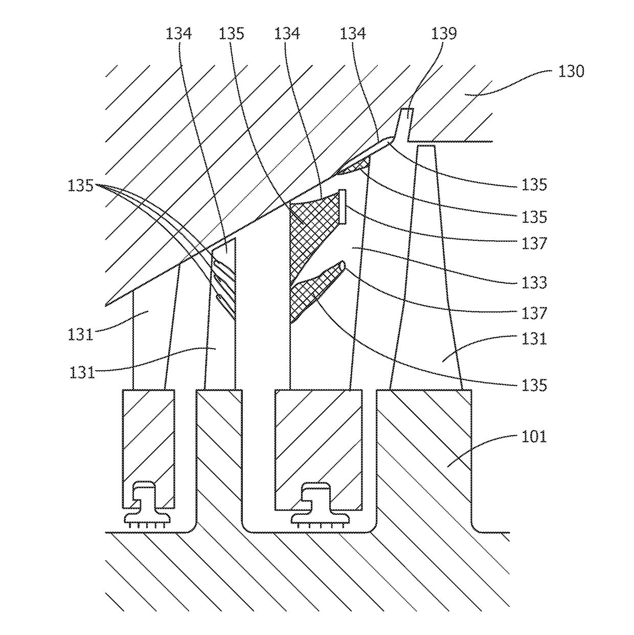
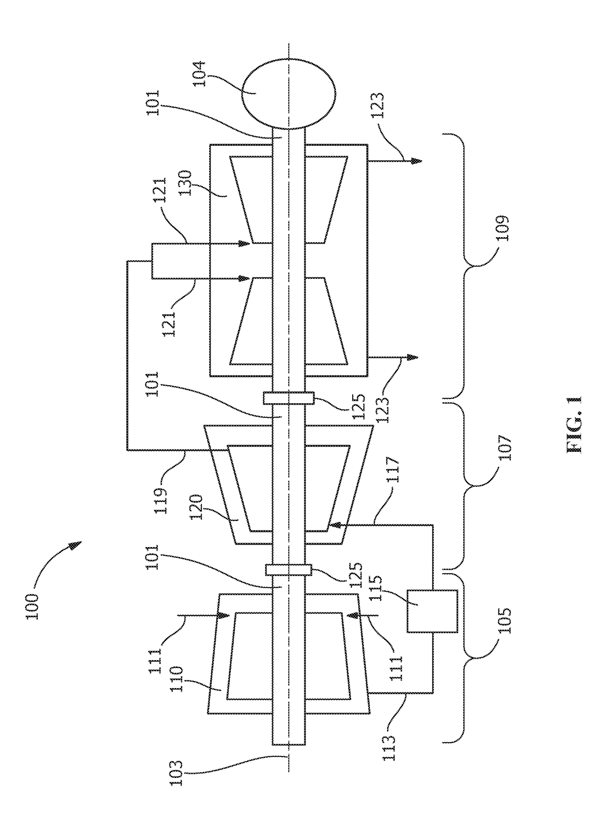
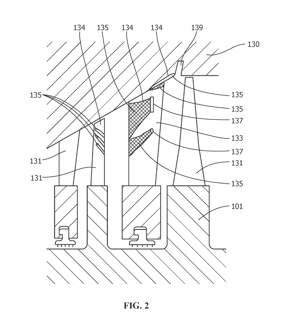
[0017]Provided is at least one hydrophilic surface pattern directing surface moisture in at least one predetermined direction in a steam turbine. In some embodiments, the hydrophilic surface pattern is a laser etched nano-scale pattern creating a hydrophilic surface. In some embodiments, the hydrophilic surface pattern creates a superhydrophilic surface. Embodiments of the present disclosure, for example, in comparison to concepts failing to include one or more of the features disclosed herein, enable enhanced moisture management by enhancing moisture removal, reducing erosion caused by moisture in a steam turbine, especially in the low pressure section, or combinations thereof.

[0018]Control of erosion in margin stage turbine buckets is desirable and often necessary. As turbine designs evolve, designers are often faced with the presence of greater amounts of moisture and the presence of new materials, some of which are difficult to protect with conventional shielding. Effectively re...


PUM

PropertyMeasurementUnit
Sizeaaaaaaaaaa
Hydrophilicityaaaaaaaaaa
Superhydrophilicityaaaaaaaaaa

Abstract

A hydrophilic surface pattern on a removal surface of a steam turbine directs surface moisture in at least one predetermined direction to enhance moisture management by enhancing moisture removal or otherwise reducing erosion caused by moisture in the steam turbine. In some embodiments, the removal surface is located on the outer surface of the nozzle wall adjacent an extraction opening. In some embodiments, the removal surface is located on the surface of the bucket and directs moisture toward the turbine rotor. In some embodiments, the removal surface is located on the surface of the turbine casing or the surface of the nozzle and directs moisture toward a drain in the turbine casing. The hydrophilic surface pattern is preferably laser-etched as a nano-scale pattern to create the hydrophilic surface. In some embodiments, the hydrophilic surface pattern creates a superhydrophilic surface.

Description

FIELD OF THE INVENTION[0001]The present invention is directed to steam turbines. More particularly, the present invention is directed to a steam turbine having a hydrophilic surface pattern for enhanced moisture management.BACKGROUND OF THE INVENTION[0002]Steam turbines extract work from a flow of steam to generate power by converting the energy of high-temperature, high-pressure steam generated by a boiler into rotational energy by supplying the steam to cascades of stationary blades (nozzles) and moving blades (buckets). A typical steam turbine may include a rotor associated with a number of wheels. The wheels may be spaced apart from each other along the length of the rotor to define a series of turbine stages. The turbine stages are designed to extract useful work from the steam traveling on a flow path from an entrance to an exit of the turbine in an efficient manner. As the steam travels along the flow path, the steam causes the wheels to drive the rotor. The steam gradually m...

Claims


Application Information

Patent Timeline
IPC IPC(8): F01D25/32F01D9/04F01D5/28
CPCF01D25/32F01D5/286F05D2300/51F05D2220/31F05D2230/10F01D9/041F01D9/02B23K26/0006B23K26/40B23K26/0624B23K26/352B23K26/361B23K26/60B23K26/3568B23K2101/001F05D2230/13F05D2240/121F05D2240/123F05D2260/602F05D2300/514F05D2300/516F05D2300/612F05D2300/613F05D2300/614Y02T50/60
Inventor FANDREI, II, THEODORE WILLIAM
Owner GENERAL ELECTRIC CO
Learn More