
Production technology for copper bar

A production process, copper rod technology, applied in the direction of manufacturing tools, metal processing equipment, workpiece cooling devices, etc., can solve the problems of high cost, poor water removal effect, multiple sets of wipers and blowers, etc., to achieve low toxicity, Prevents burning and improves moisture removal effect

Active Publication Date: 2020-05-12
HANGZHOU FUTONG ELECTRIC WIRE & CABLE
View PDF7 Cites 2 Cited by
  • Summary
  • Abstract
  • Description
  • Claims
  • Application Information

AI Technical Summary

Problems solved by technology

[0003] In view of the above problems, the present invention proposes a copper rod production process, which solves the defects of poor water removal effect, multiple sets of wipers and blowers, and high cost in the existing copper rod production process

Method used


Image

  • Production technology for copper bar
  • Production technology for copper bar
  • Production technology for copper bar

Examples


Embodiment 1

[0029] 1) Copper melting process: use a copper plate preheating furnace to melt the copper plate into molten copper;

[0030] 2) Rod casting process: casting the molten copper on the surface of the core rod to generate a cast rod;

[0031] 3) Hot-rolling process: hot-rolling the cooled cast rod to generate a copper rod;

[0032] 4) Cooling and drying process: cooling the hot-rolled copper rod with cooling water until the copper rod is cooled to 30-40°C; the cooled copper rod is dehumidified and dried by a dehumidification blowing device;

[0033] 5) Winding process: wind the above-mentioned copper rod into a circle.

Embodiment 2

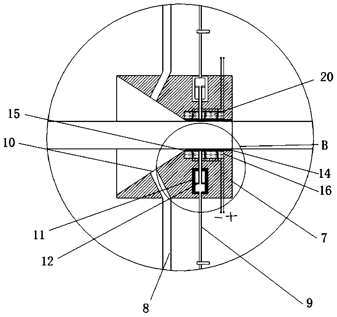
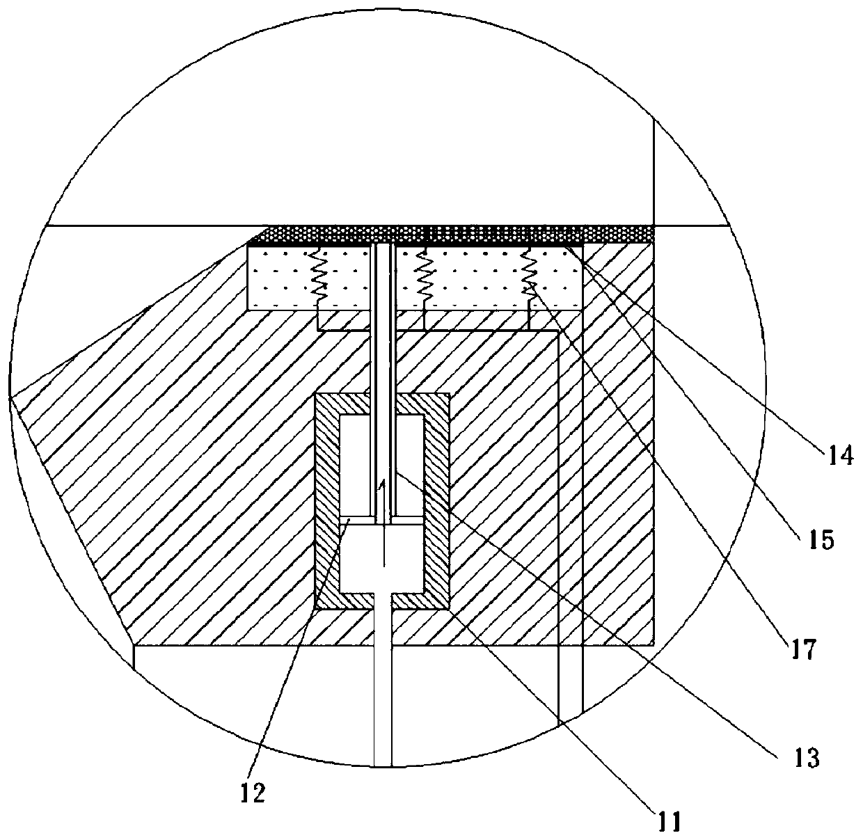
[0035] like figure 1 , figure 2 and image 3 , the present invention also discloses a dehumidification and blowing device; comprising a box body 1; a n-propanol spraying mechanism 2 and a blowing mechanism 3 are arranged in the box; the n-propanol spraying mechanism includes a n-propanol tank 4, an infusion solution Pump 5, liquid inlet main road 6, cleaning cylinder 7, first liquid inlet branch 8 and second liquid inlet branch 9, the n-propanol tank is externally connected to the liquid inlet main road, and the liquid inlet main road is externally connected to the first The liquid inlet branch and the second liquid inlet branch; an infusion pump is installed on the liquid inlet main road, a tapered feed chamber is provided at one end of the cleaning cylinder, and a spout 10 is provided on the slope of the feed chamber; The end of the first liquid inlet branch is connected to the nozzle; the copper rod 100 enters from the side of the feeding chamber and is pulled out from t...


PUM


Abstract

The invention relates to a production technology for a copper bar. The technology comprises the following steps of 1) a copper melting process; 2) a bar casting process; 3) a hot rolling process; 4) acooling and blow-drying process, wherein the hot-rolled copper bar is cooled through cooling water, and the cooled copper bar is dehumidified and blow-dried through a dehumidification and air-blowingdevice; 5) a winding process, wherein the dehumidification and air-blowing device in step 4) comprises a box; an n-propyl alcohol spraying mechanism and a blowing mechanism are arranged in the box; the blowing mechanism is used for blow-drying the wiped copper bar, and the n-propyl alcohol spraying mechanism comprises an n-propyl tank, a liquid conveying pump, a liquid inlet main pipe, a cleaningcylinder, a first liquid inlet branch pipe and a second liquid inlet branch pipe; the n-propyl tank is externally connected with the liquid inlet main pipe, and the liquid inlet main pipe is externally connected with the first liquid inlet branch pipe and the second liquid inlet branch pipe; one end of the cleaning cylinder is provided with a conical feeding cavity; and a scrubbing assembly is arranged in the cleaning cylinder. The production technology for the copper bar overcomes the defects that an existing production technology for the copper bar has a poor dewatering effect, needs multiple wipers and air blowers, and is high in cost.

Description

technical field [0001] The invention relates to the field of copper rod production, in particular to a copper rod production process. Background technique [0002] The existing oxygen-free copper rod production line with dip-coating molding method is to melt, cast, and roll electrolytic copper plates into rods, cool, blow dry, and then wind them into circles to produce bright oxygen-free copper rods for electricians. After the cooling process, if cooling water adheres to the surface of the copper rod, it will cause the copper rod to slip on the pinch roller of the winding machine. The cooling water attached to the surface of the copper rod will also cause black spots on the surface of the finished copper rod due to local oxidation; the removal effect of cooling water in the existing copper rod production process is poor, and multiple sets of wipers and blowers are required, which is costly. Contents of the invention [0003] Aiming at the above problems, the present inven...

Claims


Application Information

Patent Timeline
IPC IPC(8): B21B1/46B21B45/02
CPCB21B1/46B21B45/0215B21B45/0281B21B2045/0227
Inventor 黄晓鹏寿荣
Owner HANGZHOU FUTONG ELECTRIC WIRE & CABLE
Learn More