Eureka AIR delivers breakthrough ideas for toughest innovation challenges, trusted by R&D personnel around the world.

Fast jack hybrid liftboat hull

a hybrid and liftboat technology, applied in special-purpose vessels, vessel construction, transportation and packaging, etc., can solve the problems of inconvenient construction, high cost of downward-pointing propellers, and difficulty in equipping a standard barge hull with a functional bow thruster, etc., to achieve easy utilization, high capacity, and easy maintenance.

Inactive Publication Date: 2011-04-28
BURNS MARK L
View PDF29 Cites 0 Cited by
  • Summary
  • Abstract
  • Description
  • Claims
  • Application Information

AI Technical Summary

Benefits of technology

[0005]The direction of this design effort has been to develop a second generation of liftboat hull design that eliminates most of the problems inherent in typical prior art. The result is a hybrid hull design that is a significantly radical and improved departure from prior art. The inventive hull changes modes as the vessel's mission changes. When running in an unloaded light boat condition such as in the initial deployment of the vessel to get to the dock where it will load the equipment and crew to perform a job, or if it was mobilized for an open water crossing the boat would run in the catamaran mode with its midsection 1′ to 2′ free of the water. When the boat is loaded the weight increased the draft which brings the midsection hull in contact with the water and the extra volume increased the displacement and load carrying capacity exponentially. With the increased weight of a full deckload the catamaran becomes a barge. It will move slower as a barge but at least now it is getting paid, and it got to the job twice as fast as any other competing vessel and it will still run faster than any conventional barge. FIGS. 2 and 3 respectively show a plan and profile of a liftboat using the new hull configuration. When compared to FIG. 1 several advantages can be readily seen. In typical prior art the propellers, skegs and rudders are hanging below the keel and the thrust line is pointed downward in a compromise of draft, displacement and hull form. In this configuration the most delicate and essential parts of the vessel's hull are the most exposed to damage when transiting or operating in shallow waters, and the downward pointing propellers can cost you 10% or more in the efficiency of your applied power. The hybrid hull of FIGS. 2 and 3 makes no compromise with its straight thrust line, simple but sleek double ended hull design and in its optimum configuration it also has a flat plate extension of the hull bottom which runs under the propellers and protests them from any debris which might extend from the shallow bottom. It also functions as a pitch dampener plate when underway and a handy work platform when it is time to pull the wheels and shafts for inspection or repair. It does all of this without increasing the overall draft of the vessel. When fully loaded its draft is comparable to a conventional barge design with low hanging props and rudders. If you do run it aground the vessel's “pads” or footing which are made to be bounded off the bottom extend slightly below the hull and are the most likely part of the boat to take the impact. It is a feature that can save a lot of expensive hull damage.
[0006]The extension of the catamaran hulls below the barge hull functions as a SOLAS required double bottom without adding building costs or extra maintenance problems. Its relatively narrow bows are simply to equip with a conventional bow thruster which adds to the maneuverability and safety of the vessel. Equipping a standard barge hull with a functional bow thruster is awkward at best. Also, in the hybrid design the engines are positioned at the extreme width of the hull as can be seen in FIG. 2. This gives the boat the maximum turning torque possible to help turn and maneuver. The important of this cannot be exaggerated when you have the drag of three or four legs a hundred feet down in the water and the current is carrying you sideways into a platform or drilling rig. This is a very credible scenario as the vessel's purpose requires it to maneuver and position itself often within a few feet of pipelines and platforms to complete its work.
[0007]There are some prior designs that have the leg towers and supports partially integrated into the hull but most have the legs attached to the sides and stern. Then using sponsons and bracing as in FIG. 1, give it the strength it needs. Structural problems are common in the sponsons and hulls using this “add on” type of approach. Especially in the larger more highly stressed designs. The inventive hybrid hull fully integrates the leg towers into its basic structure. This is a continuous box beam which forms a square that runs between the four legs (see FIG. 4). Very simple, very strong, very easy to build. The integrated leg tower also means that your precious jacking machinery and hoses can be below deck, safe from exposure to the effects of sun and saltwater, without having to build additional space robbing, heavy and expensive structures around the leg.

Problems solved by technology

In this configuration the most delicate and essential parts of the vessel's hull are the most exposed to damage when transiting or operating in shallow waters, and the downward pointing propellers can cost you 10% or more in the efficiency of your applied power.
Equipping a standard barge hull with a functional bow thruster is awkward at best.
Structural problems are common in the sponsons and hulls using this “add on” type of approach.
At first glance the inventive hybrid hull might seem more complicated and expensive to construct.

Method used


Image

  • Fast jack hybrid liftboat hull
  • Fast jack hybrid liftboat hull
  • Fast jack hybrid liftboat hull

Examples


Embodiment Construction

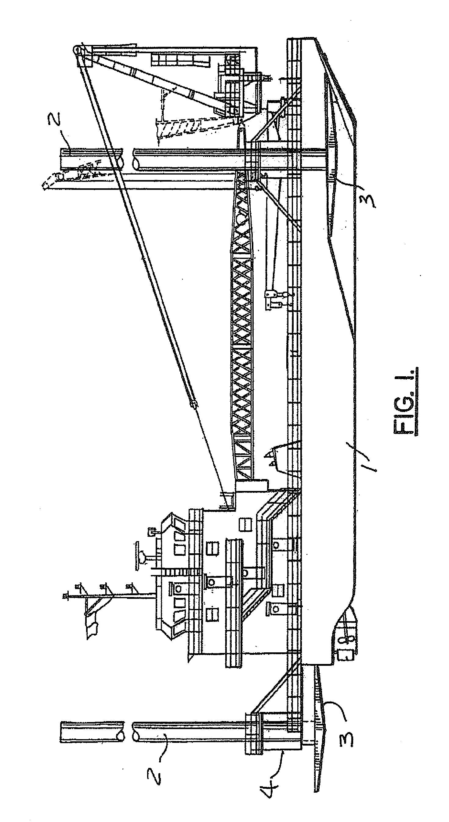
[0023]FIG. 1 depicts an outboard profile of a typical liftboat as currently known in the art. Shown is the hull 1, the legs 2, the pads 3, the jacking towers 4, sponsons 5, while the actual jacking system is not shown.

[0024]Referring to FIG. 1, the disadvantages of current liftboat design and construction are apparent. Construction of sponsons and overhangs is unnecessarily complicated and inherently weaker than an integrated design. Compound curve of stern rake is difficult to construct / repair. Having the keel coolers on inside of hull creates several problems including corrosion of piping and electrical wiring inside wet tanks and voids. Catch water in pockets can cause localized corrosion, creating the need to repair or cut out and replace sections in hard to reach places. This means down time and repair expenses compounded by damage done to the inside of the engine room trying to replace cooler under a generator set or engine. Internal coolers make it hard to clean and rinse the...


PUM


Abstract

A liftboat with an improved hybrid hull which increases the speed and efficiency of the vessel and reduces the changes of damage should an accidental grounding occur with box beam construction, starboard and port catamaran hulls, a center barge hull, multiple legs, a jacking system for moving each upward and downward, and a retractable local bearing pad for each leg that engaged the seabed when in use. In addition, it proves a more streamlined housing for the retracted pads and a stronger integrated structure for the leg towers which guide and support the legs.

Description

[0001]This application claims priority from U.S. Provisional application Ser. No. 61 / 201,958 (“the '958 application”) filed Dec., 16, 2008. The '958 application is incorporated herein by reference.FIELD OF THE INVENTION[0002]This application relates to self-elevating boats known as Jack Up Boats / Jack Up Barges / Self Elevating Work Platforms or SEWOPS, used primarily in the oil and gas industry. More specifically, the present invention relates to a liftboat with an improved hull which increases the speed and efficiency of the vessel and reduces the changes of damage should an accidental grounding occur. In addition, it proves a more streamlined housing for the retracted pads and a stronger integrated structure for the leg towers which guide and support the legs.BACKGROUND AND FIELD OF INVENTION[0003]In the shallow coastal waters of the Gulf of Mexico, the oil industry has numerous small platforms and require maintenance and repair but have no space or facilities to accommodate the men...

Claims


Application Information

Patent Timeline
Patent Type & Authority Applications(United States)
IPC IPC(8): B63B1/10B63B35/44
CPCB63B35/44
Inventor BURNS, MARK L.
Owner BURNS MARK L
Why Eureka
Eureka Blog
Learn More