Combination of fastener and thermal-conducting member

a technology of fasteners and thermal conductors, which is applied in the direction of semiconductor devices, semiconductor/solid-state device details, lighting and heating apparatus, etc., can solve the problems of deteriorating thermal conductivity effect and warping of fasteners, and achieves the effect of increasing the vertical height of the whole combination, simplifying manufacturing and assembly process, and strengthening the fastening effect of fasteners

Inactive Publication Date: 2011-04-28
CELSIA TECH TAIWAN INC
View PDF13 Cites 8 Cited by
  • Summary
  • Abstract
  • Description
  • Claims
  • Application Information

AI Technical Summary

Benefits of technology

[0011](1) Since the clamping arms of the fastener are inserted into the positioning notches of the thermal-conducting member, the thermal-conducting member may not slide with respect to the fastener. Further, the clamping arms and the positioning notches are soldered together. Thus, with dual effects of mechanical clamping and soldering, the fastener and the thermal-conducting member can be assembled together to form a structure that is more rigid to resist the warping of the fastener. Thus, during the process of securing the screws on the circuit board, the problem in prior art that the fastener may warp to be separated from the thermal-conducting member can be overcome.
[0012](2) Since the clamping arms are inserted into the positioning notches with the top surfaces of the clamping arms being in flush with the top surface of the thermal-conducting member, such an arrangement can strengthen the fastening effect of the fastener without increasing the vertical height of the whole combination on the circuit board. Thus, it conforms to the requirement for compactness.
[0013](3) According to the present invention, the clamping arms of the fastener can be bent directly to press in the thermal-conducting member by a larger pressing force, thereby forming the positioning notches on the surface of the thermal-conducting member until the top surfaces of the clamping arms are in flush with the top surface of the thermal-conducting member. In this way, the fastener can be assembled with the thermal-conducting member tightly, and it is unnecessary to form the positioning notches on the thermal-conducting member in advance, which simplifies the manufacturing and assembling process.

Problems solved by technology

During the fixing process of the screws, if the fixing force of the screw is larger than a feedback force exerted by a chip, the fastener may be warped due to the uneven fixing forces of the screws.
As a result, the thermal-conducting member may be separated from the fastener, so that the thermal-conducting member cannot contact the electronic heat-generating element tightly, which will deteriorate the thermal-conducting effect.

Method used


Image

  • Combination of fastener and thermal-conducting member
  • Combination of fastener and thermal-conducting member
  • Combination of fastener and thermal-conducting member

Examples


Embodiment Construction

[0020]The characteristics and technical contents of the present invention will be explained with reference to the accompanying drawings. However, the drawings are illustrative only but not used to limit the present invention.

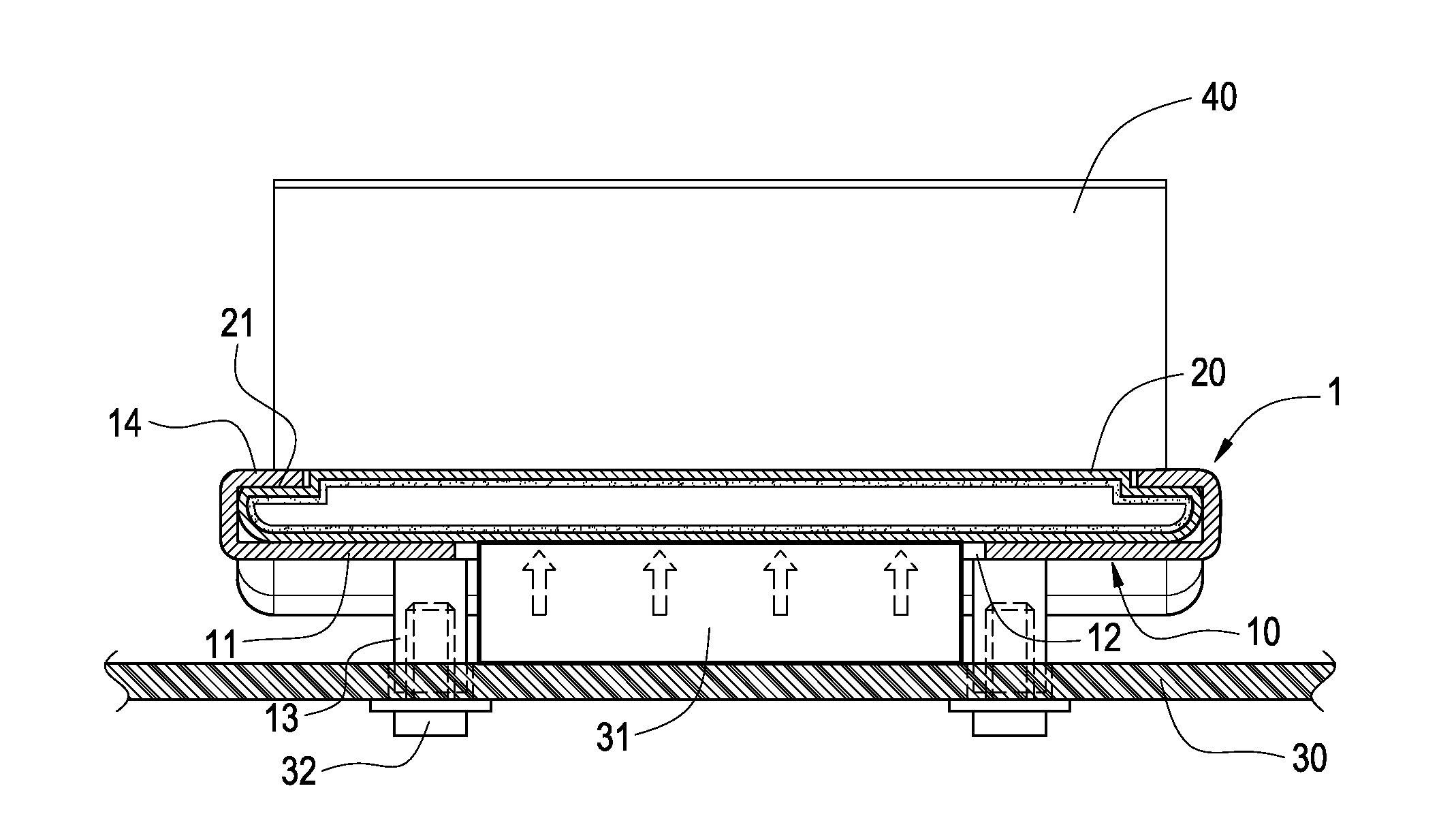
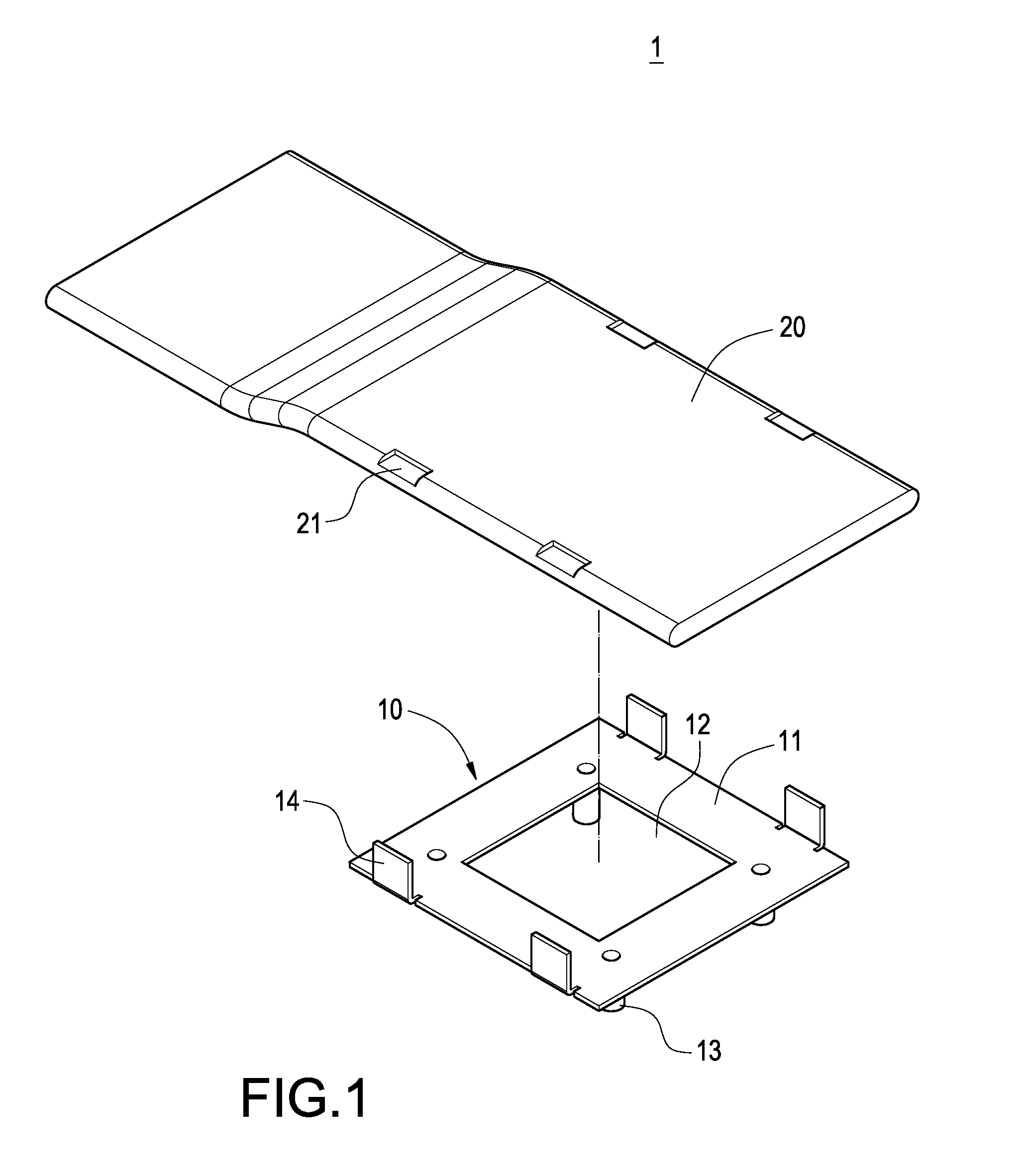
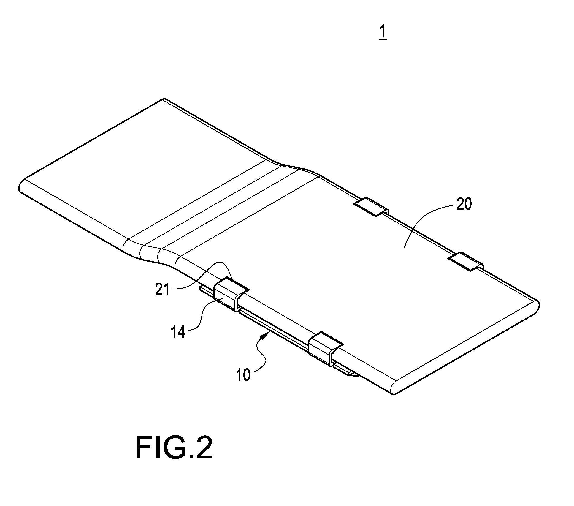
[0021]Please refer to FIGS. 1 to 3. FIG. 1 is an exploded perspective view of the present invention. FIG. 2 is an assembled perspective view of the present invention, and FIG. 3 is an assembled perspective view of the present invention taken from another viewing angle. The present invention provides a combination 1 of a fastener and a thermal-conducting member, which includes a fastener 10 and a thermal-conducting member 20. As shown in FIG. 5, the combination 1 is mounted on a circuit board 30 of an electronic heat-generating element 31 by means of screws 32. With this combination 1, the heat of the electronic heat-generating element 31 can be dissipated to the outside quickly, thereby keeping the working temperature of the electronic heat-generating element 31...


PUM


Abstract

A combination of a fastener and a thermal-conducting member is mounted on an electronic heat-generating member. The fastener includes a plate provided with an opening for allowing the electronic heat-generating element to be disposed therein; posts connected to the plate and formed around the opening; and clamping arms extending from the plate opposite to the posts. The thermal-conducting member is disposed on the plate to span the opening. The clamping arms are bent to press in the thermal-conducting member, thereby forming on the surface of the thermal-conducting member with a plurality of positioning notches for allowing the clamping arms to be inserted therein. With this arrangement, the fastener can be combined with the thermal-conducting member tightly. Thus, the heat generated by the electronic heat-generating element can be continuously conducted to the outside, so that the temperature of the electronic heat-generating element can be kept in a normal range.

Description

BACKGROUND OF THE INVENTION[0001]1. Field of the Invention[0002]The present invention relates to a combination of a fastener and a thermal-conducting member, and in particular to a combination of a fastener and a thermal-conducting member that is mounted on an electronic heat-generating element.[0003]2. Description of Prior Art[0004]With the advancement of science and technology, the power of an electronic heat-generating element (such as a CPU) increases significantly. As a result, the heat generated by the electronic heat-generating element is increased greatly. Thus, a heat sink with stronger heat-dissipating effect is needed to dissipate the heat generated by the electronic heat-generating element, so that the normal operation of the electronic heat-generating element may not be affected. A conventional way of dissipating the heat generated by the electronic heat-generating element is to secure a heat sink by a fastener to a circuit board on which the electronic heat-generating ...

Claims


Application Information

Patent Timeline
Patent Type & Authority Applications(United States)
IPC IPC(8): H01L23/40F28F7/00
CPCF28D15/0233H01L23/427H01L2924/0002H01L2924/00
Inventor MEYER, IV, GEORGE ANTHONYSUN, CHIEN-HUNGCHEN, CHIEH-PING
Owner CELSIA TECH TAIWAN INC
Why Eureka
Try Eureka