Power Cord with Thermal Control
- Summary
- Abstract
- Description
- Claims
- Application Information
AI Technical Summary
Benefits of technology
Problems solved by technology
Method used
Image
Examples
Embodiment Construction
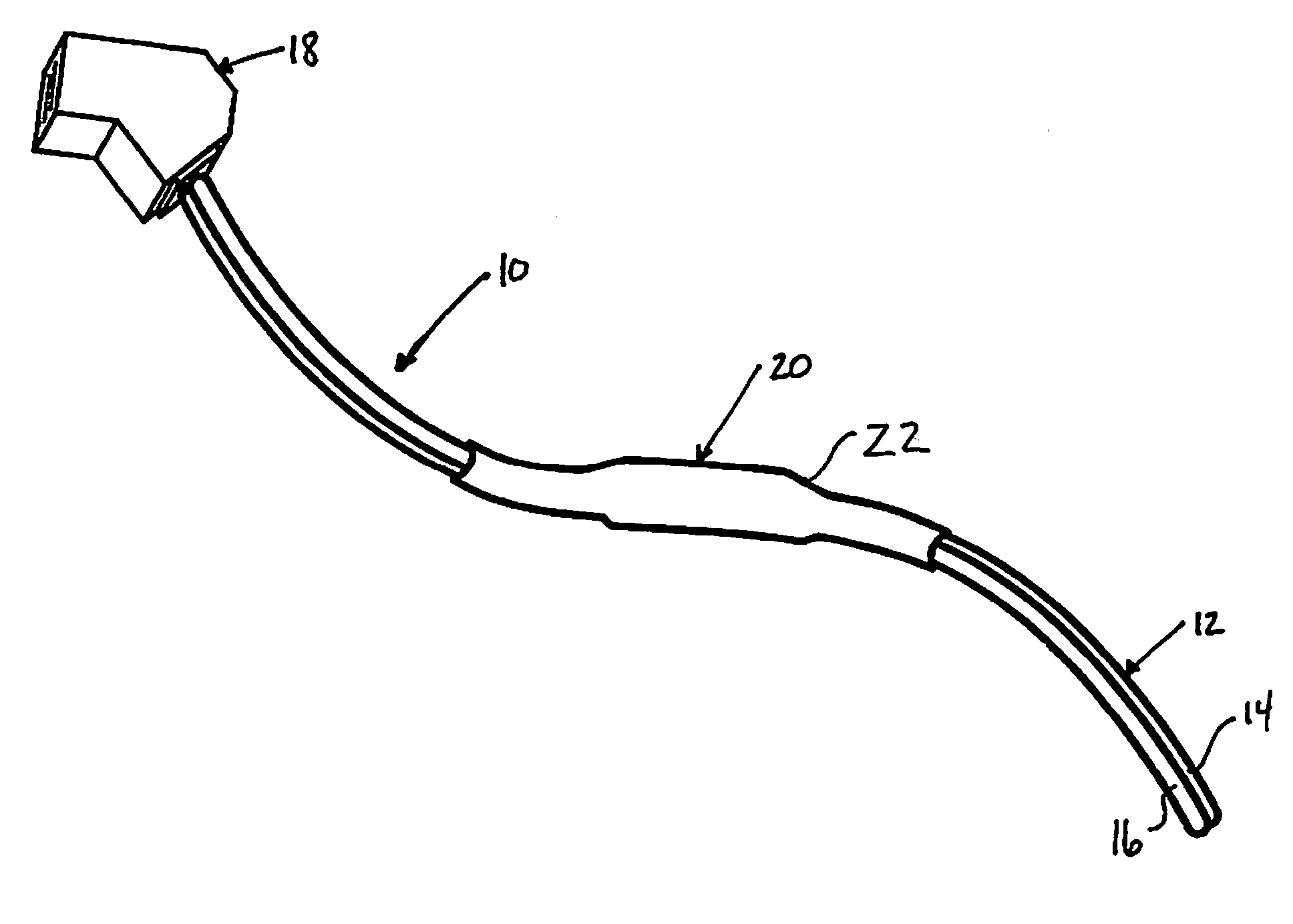
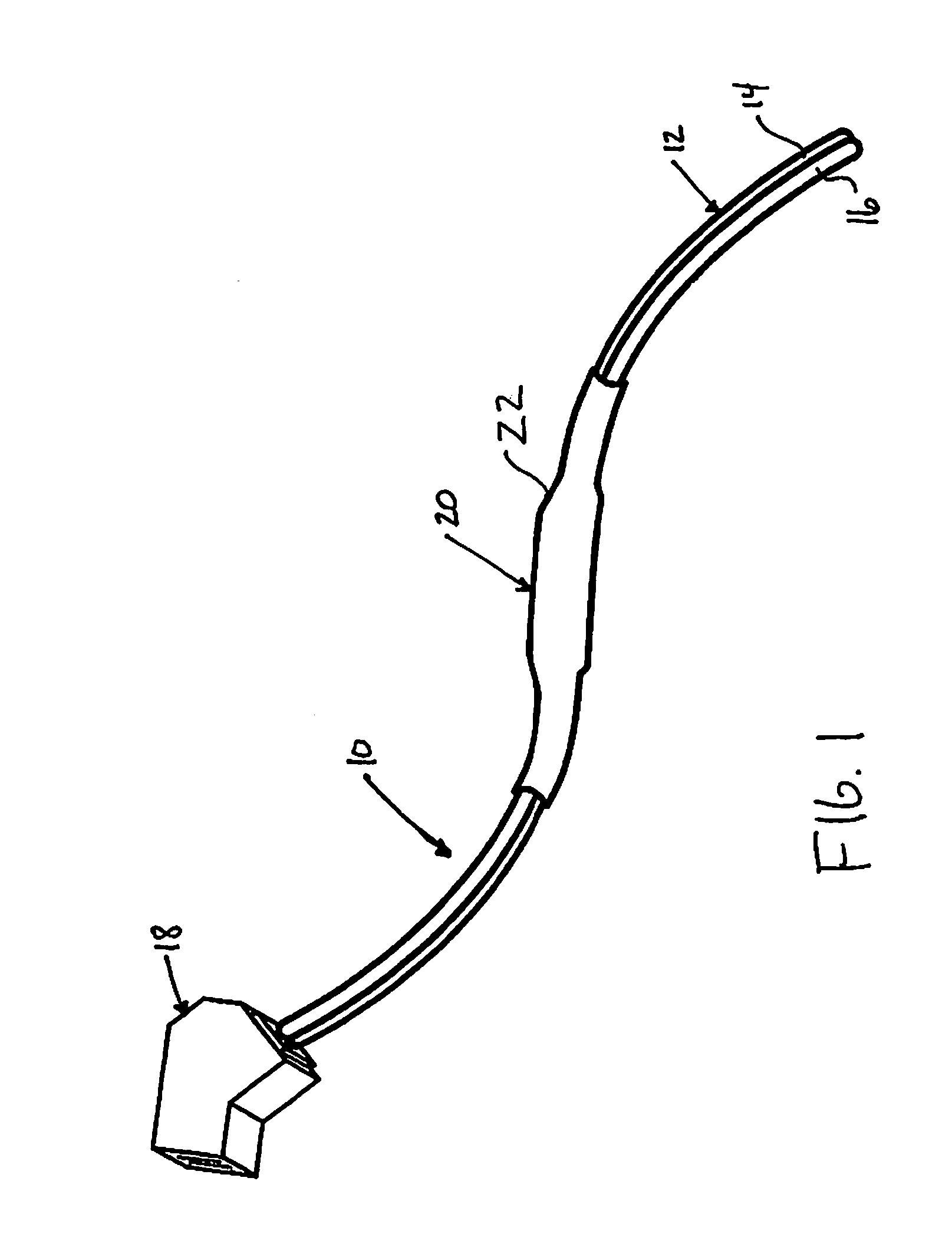
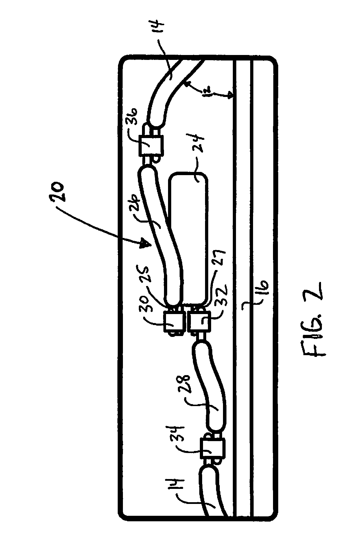
[0025]Referring to FIG. 1, the illustrated power cord with thermal control 10 comprises a wire 12 having multiple conductors, and as illustrated in one preferred embodiment, two conductors 14, 16 with connector 18 at one end. A heat reactive or thermal element 20 is connected to one of the multiple conductors, as shown in FIG. 1, conductors 14, 16, and surrounded by shrink tubing 22 to attach thermal element 20 to the power cord 10 as shown. As can be seen in one preferred embodiment of FIG. 1, thermal element 20 is axially aligned and integral with wire 12 and conductors 14, 16 of power cord 10 to provide flexibility thereby preventing restriction in movement of power cord 10, including wire 12. Thermal element 20 is configured and positioned on wire 12 to be placed within a housing of an electrical device to detect or read ambient temperature within the housing.
[0026]The cost of energy continues to rise throughout the world. The average cost of electricity in the United States is ...
PUM
 Abstract
Description
Claims
Application Information
 - R&D
- Intellectual Property
- Life Sciences
- Materials
- Tech Scout
- Unparalleled Data Quality
- Higher Quality Content
- 60% Fewer Hallucinations
Browse by: Latest US Patents, China's latest patents, Technical Efficacy Thesaurus, Application Domain, Technology Topic, Popular Technical Reports.
© 2025 PatSnap. All rights reserved.Legal|Privacy policy|Modern Slavery Act Transparency Statement|Sitemap|About US| Contact US: help@patsnap.com


