Wireless sensor apparatus

a sensor and wireless technology, applied in the field of wireless sensor apparatus, can solve the problems of increasing the size of the apparatus, difficult to meet both the antenna reception sensitivity and the miniaturization of the apparatus, and achieve the effect of reducing the peak power required for the oscillator

Active Publication Date: 2011-04-28
ALPS ALPINE CO LTD
View PDF7 Cites 5 Cited by
  • Summary
  • Abstract
  • Description
  • Claims
  • Application Information

AI Technical Summary

Benefits of technology

[0010]Embodiments of the present disclosure have been made in view of the above-mentioned problem and provide a wireless sensor apparatus capable of securing an isolation between antennas without an interference of mutual wireless waves between a plurality of antennas, realizing a miniaturization of the apparatus, and also reducing a peak power demanded for an oscillator by half.
[0012]According to this configuration, after the prior pulse signal is fed to the first antenna and simultaneously supplied to the first mixer circuit, at a proximate timing which does not overlap with the pulse width of the prior pulse signal supplied to the first antenna and the first mixer circuit, the next pulse signal is fed to the second antenna and simultaneously supplied to the second mixer circuit. Therefore, the supply timing for the pulse signal to the first antenna is not overlapped with the supply timing for the pulse signal to the second transmission antenna. Therefore, it is possible to secure the isolation between the antennas without the interference caused by the mutual wireless waves between the plurality of antennas A11 and A12, and also it is possible to realize the miniaturization of the apparatus as the distance between the antennas does not need to be increased. Also, the pulse signals are fed from the signal generation circuit to the first and second antennas at different timings, and therefore as compared with the wireless sensor apparatus in related art, it is possible to reduce the peak power demanded for the oscillator by half.
[0014]According to this configuration, as the antenna which becomes the feed destination of the pulse signal is switched between the first and second antennas in synchronization with the generation timing for the pulse signal set in the timing circuit, the supply timings for the pulse signals to the respective antennas can be switched. For that reason, the radiation timings for the wireless waves from the respective antennas are not overlapped with each other, and it is possible to prevent the interference of the wireless waves radiated from the respective antennas.
[0016]According to this configuration, as the proximate timing is the timing when the time twice the pulse width elapses from the rise of the prior pulse signal, when both the pulse signals are repeatedly generated, it is possible to continuously radiate the wireless waves from the respective antennas. Therefore, by analyzing the reflected waves continuously reflected, it is possible to detect the motion of the object moving at a high speed.

Problems solved by technology

However, in the wireless sensor apparatus 1 shown in FIG. 4, as the transmission and reception antennas A1 and A2 are supplied with the pulse signals at the same time from the RF oscillating circuit 2, a problem occurs in which the wireless waves radiated from the respective antennas A1 and A2 at the same time function as mutual disturbing waves for causing an interference.
However, in a case where a distance between the antennas is increased to cancel the interference, the size of the apparatus becomes larger, and therefore a problem occurs in which it is difficult to satisfy both the antenna reception sensitivity and a miniaturization of the apparatus.

Method used


Image

  • Wireless sensor apparatus
  • Wireless sensor apparatus
  • Wireless sensor apparatus

Examples


Embodiment Construction

[0022]The following description is intended to convey a thorough understanding of the embodiments described by providing a number of specific embodiments and details involving a wireless sensor apparatus. It should be appreciated, however, that the present invention is not limited to these specific embodiments and details, which are exemplary only. It is further understood that one possessing ordinary skill in the art, in light of known systems and methods, would appreciate the use of the invention for its intended purposes and benefits in any number of alternative embodiments, depending on specific design and other needs.

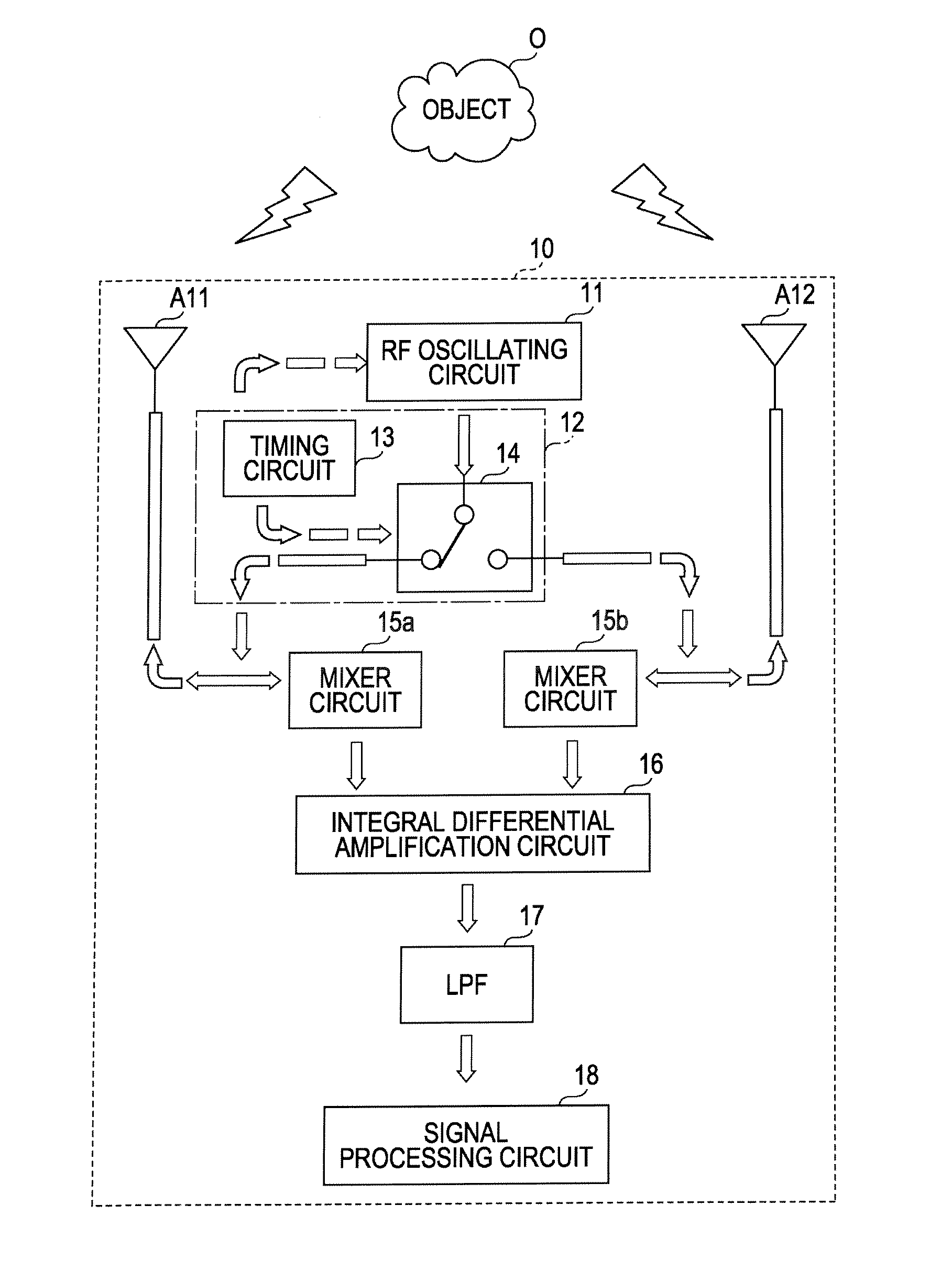
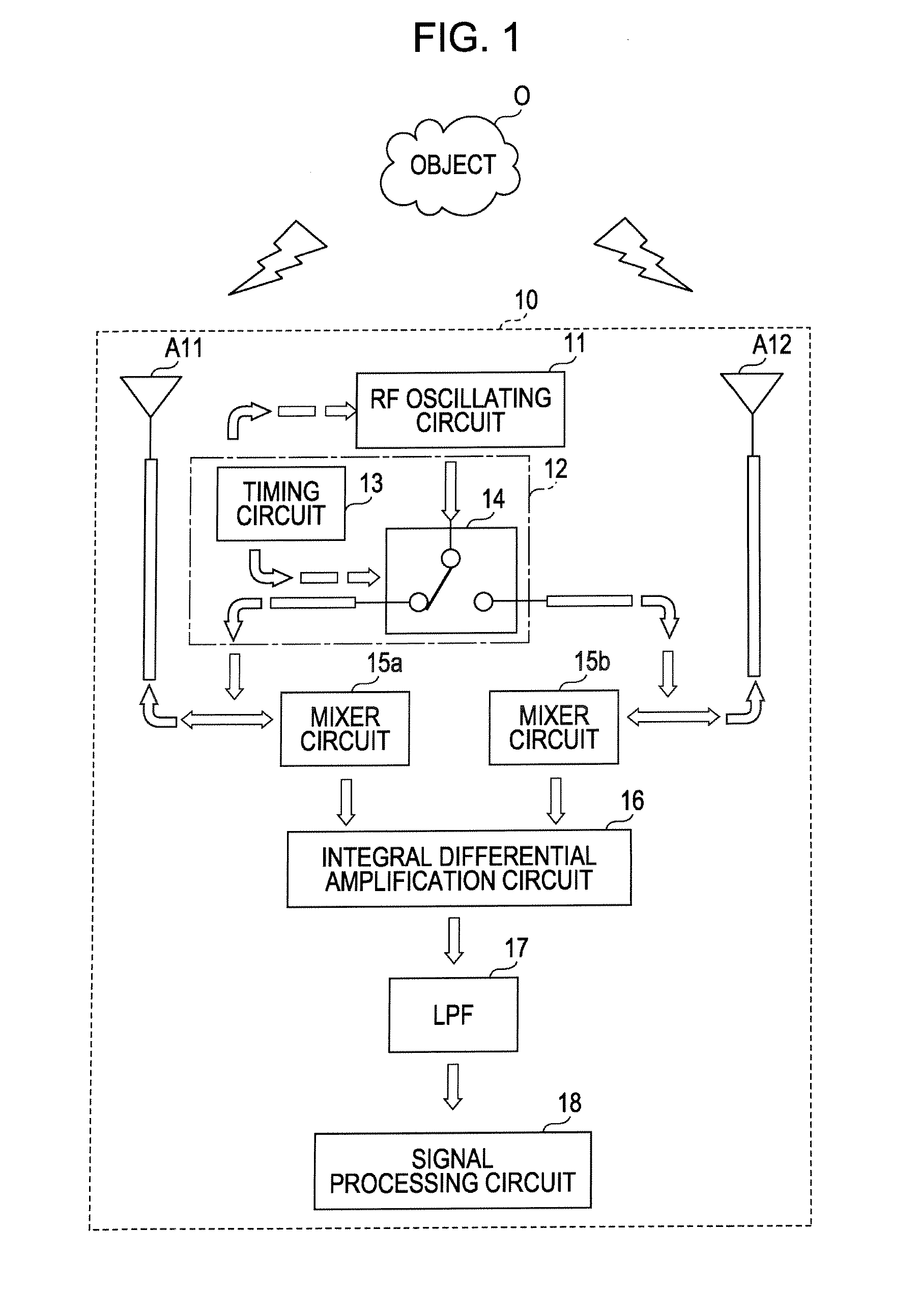
[0023]Hereinafter, with reference to the accompanying drawings, various embodiments of the present disclosure will be described in detail. A wireless sensor apparatus according to an embodiment is provided with a plurality of antennas for transmission and reception and may be configured to feed pulse signals generated by an RF oscillating circuit to the respective ...


PUM


Abstract

A wireless sensor apparatus controls, in a case where wireless waves are radiated by feeding pulse signals generated by a signal generation circuit to antennas, an operation timing of the signal generation circuit and a path from the signal generation circuit to the antennas in such a manner that after a prior pulse signal is fed to the antenna and simultaneously supplied to a mixer circuit, at a proximate timing which does not overlap with a pulse width of the prior pulse signal supplied to the antenna and the mixer circuit, a next pulse signal is fed to the antenna and simultaneously supplied to a mixer circuit.

Description

CLAIM OF PRIORITY[0001]This application claims benefit of Japanese Patent Application No. 2009-246584 filed on Oct. 27, 2009, which is hereby incorporated by reference in its entirety.BACKGROUND OF THE DISCLOSURE[0002]1. Field of the Disclosure[0003]Embodiments of the present disclosure relate to a wireless sensor apparatus for detecting a motion or the like of an object on the basis of a reflected wave of the object by using a wireless wave.[0004]2. Description of the Related Art[0005]Japanese Unexamined Patent Application Publication No. 2004-245602 discloses an apparatus which is configured to feed an output signal from an oscillator to an antenna for radiating a wireless wave, receive a reflected wave obtained while this wireless wave is reflected by an object, and detect an orientation and a motion of the object on the basis of the received reflected wave).[0006]FIG. 4 shows a wireless sensor apparatus configured to detect a motion or the like of an object by using a pulse sign...

Claims


Application Information

Patent Timeline
Patent Type & Authority Applications(United States)
IPC IPC(8): G01S13/00
CPCG01S7/025G01S13/56G01S7/282
Inventor YUANZHU, DOU
Owner ALPS ALPINE CO LTD
Why Eureka
Try Eureka