Droplet discharge device and method for controlling droplet discharge device

a technology of droplet discharge and droplet, which is applied in the direction of printing, other printing apparatus, etc., can solve the problems of image recognition (discharge inspection) being carried out, affecting the processing time of workpieces, and time constraints on inspection details, so as to achieve the effect of improving productivity

Active Publication Date: 2011-04-28
TOKYO ELECTRON LTD
View PDF1 Cites 14 Cited by
  • Summary
  • Abstract
  • Description
  • Claims
  • Application Information

AI Technical Summary

Benefits of technology

[0009]An object of the present invention is to provide, first, a droplet discharge device and a method for controlling a droplet discharge device whereby discharge inspection of a droplet discharge head can be carried out without affecting the takt time of processing the workpiece and without being subject to time constraints; and, second, a droplet discharge device and a method for controlling a droplet discharge device whereby the takt time of processing the workpiece device can be reduced and sufficient time can be taken for discharge inspection of the functional droplet discharge head.Single Stage Configuration
[0045]According to this configuration, in cases in which the weight of the discharged functional liquid must be measured, such as when the functional droplet discharge head is replaced (a carriage is replaced), this measurement can be carried out on the movement mechanism, and productivity can be improved.

Problems solved by technology

However, with this type of droplet discharge device, since the target unit is disposed between the workpiece table and the periodic flushing box, inspection discharge can be carried out in continuation with the drawing action by including the inspection data in the drawing data, but there has been a restriction in that the image recognition (discharge inspection) can be carried out only during the workpiece placement / removal action.
Therefore, in cases in which the discharge inspection is longer than the time duration of the placement / removal action, it affects the takt time of processing the workpiece.
Conversely, if the intention is to preserve the takt time, there is a problem with time constraints on the inspection details.

Method used


Image

  • Droplet discharge device and method for controlling droplet discharge device
  • Droplet discharge device and method for controlling droplet discharge device
  • Droplet discharge device and method for controlling droplet discharge device

Examples


first embodiment

Single Stage

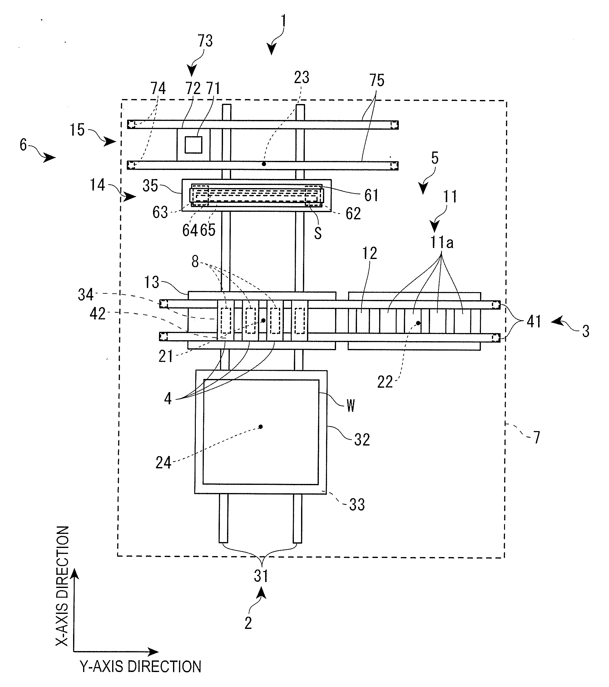
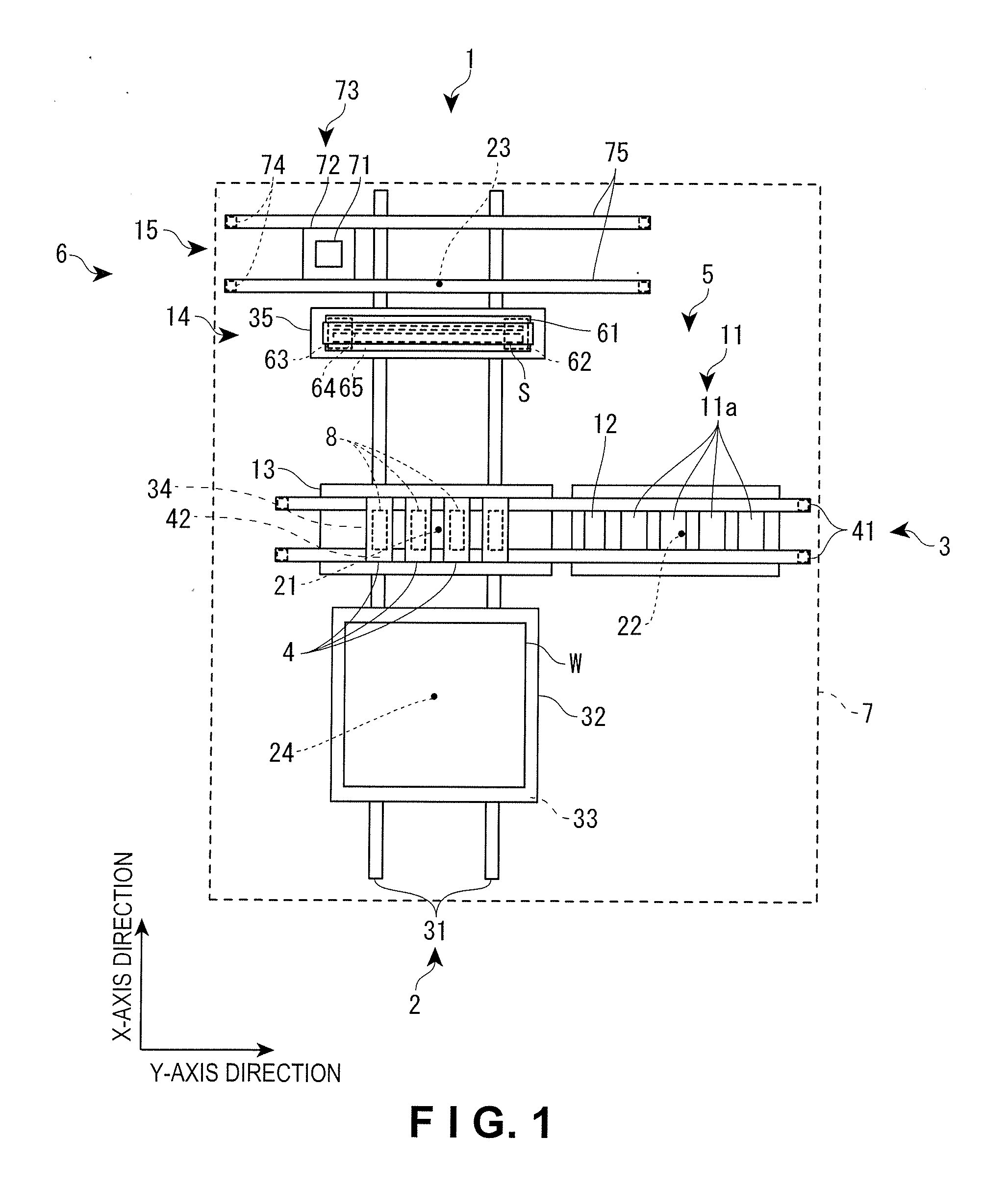
[0060]As shown in FIG. 1, the droplet discharge device 1 is composed of an X-axis table 2 for moving a workpiece W in the X-axis direction, the X-axis table 2 extending in the X-axis direction as the primary scanning direction during drawing; a Y-axis table 3 erected so as to span across the X-axis table 2 and made to extend in the Y-axis direction as a secondary scanning direction during drawing; and thirteen carriage units 4 in which a plurality of (twelve) functional droplet discharge heads 8 is mounted, the carriage units 4 being suspended by the Y-axis table 3 so as to be able to move. By selectively driving the discharge of the functional droplet discharge heads 8 synchronously with the driving of the X-axis table 2 and the Y-axis table 3, the droplet discharge device 1 draws on the workpiece W on the basis of a predetermined drawing pattern. Only four carriage units 4 are shown in the drawings, and only one functional droplet discharge head 8 is shown in each carr...

second embodiment

Double Stage

[0097]Next, the droplet discharge device 1 according to the second embodiment of the present invention will be described with reference to FIGS. 7 through 10. The description primarily focuses on components different from the first embodiment in order to avoid superfluous description. As shown in FIG. 7, the droplet discharge device 1 includes a pair of positioning stages 32 (first and second positioning stages), an X-axis table 2 for primarily moving a workpiece W alternately in the X-axis direction via the pair of positioning stages 32, the X-axis table 2 extending in the X-axis direction; a Y-axis table 3 erected so as to span across the X-axis table 2 and made to extend in the Y-axis direction; and thirteen carriage units 4 in which a plurality of (twelve) functional droplet discharge heads 8 is mounted, the carriage units 4 being suspended by the Y-axis table 3 so as to be able to move. In the present embodiment, the movement mechanism mentioned in the claims is con...


PUM


Abstract

A droplet discharge device is adapted to perform drawing of droplets of functional liquid from a functional droplet discharge head onto a workpiece in a drawing area, and to perform discharge inspection of the functional droplet discharge head in an inspection area, which is separated from the drawing area. The droplet discharge device includes a positioning stage, a flushing unit and an inspection stage disposed in this order along a common movement axis passing through the drawing area and the inspection area so that the inspection stage is disposed at a position closer to the inspection area. An image recognition device is disposed in the inspection area. A movement mechanism is arranged to move the positioning stage, the flushing unit and the inspection stage along the common movement axis. The movement mechanism is arranged to move the inspection stage independently of the positioning stage and the flushing unit.

Description

CROSS-REFERENCE TO RELATED APPLICATIONS[0001]This application claims priority to Japanese Patent Application No. 2009-245203 filed on Oct. 26, 2009 and Japanese Patent Application No. 2010-046143 filed on Mar. 3, 2010. The entire disclosures of Japanese Patent Application Nos. 2009-245203 and 2010-046143 are hereby incorporated herein by reference.BACKGROUND[0002]1. Technical Field[0003]The present invention relates to a droplet discharge device and to a method for controlling a droplet discharge device, wherein drawing on a workpiece by a functional droplet discharge head and inspection of the functional droplet discharge head are performed along a common movement axis.[0004]2. Related Art[0005]An example known in the art of a droplet discharge device of such description is one in which discharge inspection of the functional droplet discharge head is performed while a workpiece is being placed or removed (see Japanese Laid-Open Patent Publication No. 2009-6212).[0006]This droplet d...

Claims


Application Information

Patent Timeline
Patent Type & Authority Applications(United States)
IPC IPC(8): B41J29/393
CPCB41J2/16579B41J2/1652
Inventor ITO, YOSHIHIRO
Owner TOKYO ELECTRON LTD
Why Eureka
Try Eureka