Broadcast receiver system

a receiver and broadcast technology, applied in the field of broadcast receivers, can solve the problems of increasing development costs, many dedicated solutions are undesirable, complicated digital tv situation,

Inactive Publication Date: 2011-04-28
MIRICS SEMICON
View PDF25 Cites 8 Cited by
  • Summary
  • Abstract
  • Description
  • Claims
  • Application Information

AI Technical Summary

Benefits of technology

[0020]According to one embodiment of the invention there is provided an interface implemented at least partly in computer code and configured to connect between (a) a demodulator implemented in software on the general purpose computing device and (b) an interface circuit associated with a separate hardware tuner for receiving broadcast signals. The interface comprises: a data interface for receiving packetised signal sample data including header information comprising control settings indications which are applied during taking of the sample data; a control interface operable to receive control instructions from tuner control code, setting control inputs of configurable tuner components and further operable to forward said control instructions to a complimentary interface associated with the tuner circuitry; tuner control code operable to issue control instructions intended to change a control setting of a configurable component of the tuner circuitry; a log of at least one issued instruction; and a packet monitoring module operable to detect control settings indications for configurable components of the tuner and to compare them with the log to determine when an instruction issued by the tuner control code has been implemented at the configurable component of the tuner circuitry.
[0021]According to one embodiment of the invention there is provided an interface implemented at least partly in computer code and configured to connect between (a) a demodulator implemented in software on the general purpose computing device and (b) an interface circuit associated with a separate hardware tuner for receiving broadcast signals. The interface comprises: a data interface for receiving packetised signal sample data including header information comprising control settings indications, which applied during taking of the sample data; a control interface operable to receive control instructions from tuner control code, setting control inputs of configurable tuner components and further operable to forward said control instructions to a complimentary interface associated with the tuner circuitry; tuner control code operable to issue control instructions intended change a control setting of a configurable component of the tuner circuitry; a timer module recording time since instruction issue, operable to determine that an instruction issued by the tuner control code has been implemented at the configurable component of the tuner circuitry a predetermined period after issue.
[0022]According to another embodiment of the invention the tuner control code is configured to issue instructions applying to an analogue to digital converter associated with the tuner circuit and a detected indication comprises a data sampling rate applying in respect of the signal sample data.
[0023]According to another embodiment of the invention the tuner control code is configured to issue instructions applying to frequency selection of the tuner and a detected indication comprises a tuner frequency applying in respect of the signal sample data.
[0024]According to another embodiment of the invention the tuner control code is configured to issue instructions relating to amplifier again of the tuner and a detected indication comprises a gain value applying in respect of the signal sample data.

Problems solved by technology

However, different countries use different types of broadcast standard for both television and radio signals, most of which are to varying extents incompatible with each other.
However, the digital TV situation is complicated by the fact that digital standards differ significantly in the details of how the MPEG-2 stream is converted into a broadcast signal, and ultimately how it is decoded for viewing.
However, having many dedicated solutions is undesirable for a number of reasons.
For example, having receiver hardware customized for each standard increases the development costs and ultimately means that each individual product is tied to one standard, often operable in only one region.
The upshot is that currently known technology is generally inflexible as well as expensive to make.
No currently known technology provides a multi-standard broadcast receiver which is compatible with any global transmission standard and easily upgraded to future standards.
Furthermore, no currently known technology provides a broadcast receiver which utilizes general purpose computer hardware in order to efficiently reduce development, manufacturing and implementation costs.

Method used


Image

  • Broadcast receiver system
  • Broadcast receiver system
  • Broadcast receiver system

Examples


Embodiment Construction

[0038]Those skilled in the art will appreciate that while this disclosure describes what is considered to be the best mode and, where appropriate, other modes of performing the invention, the invention should not be limited to the specific configurations and methods disclosed in this description of the preferred embodiment.

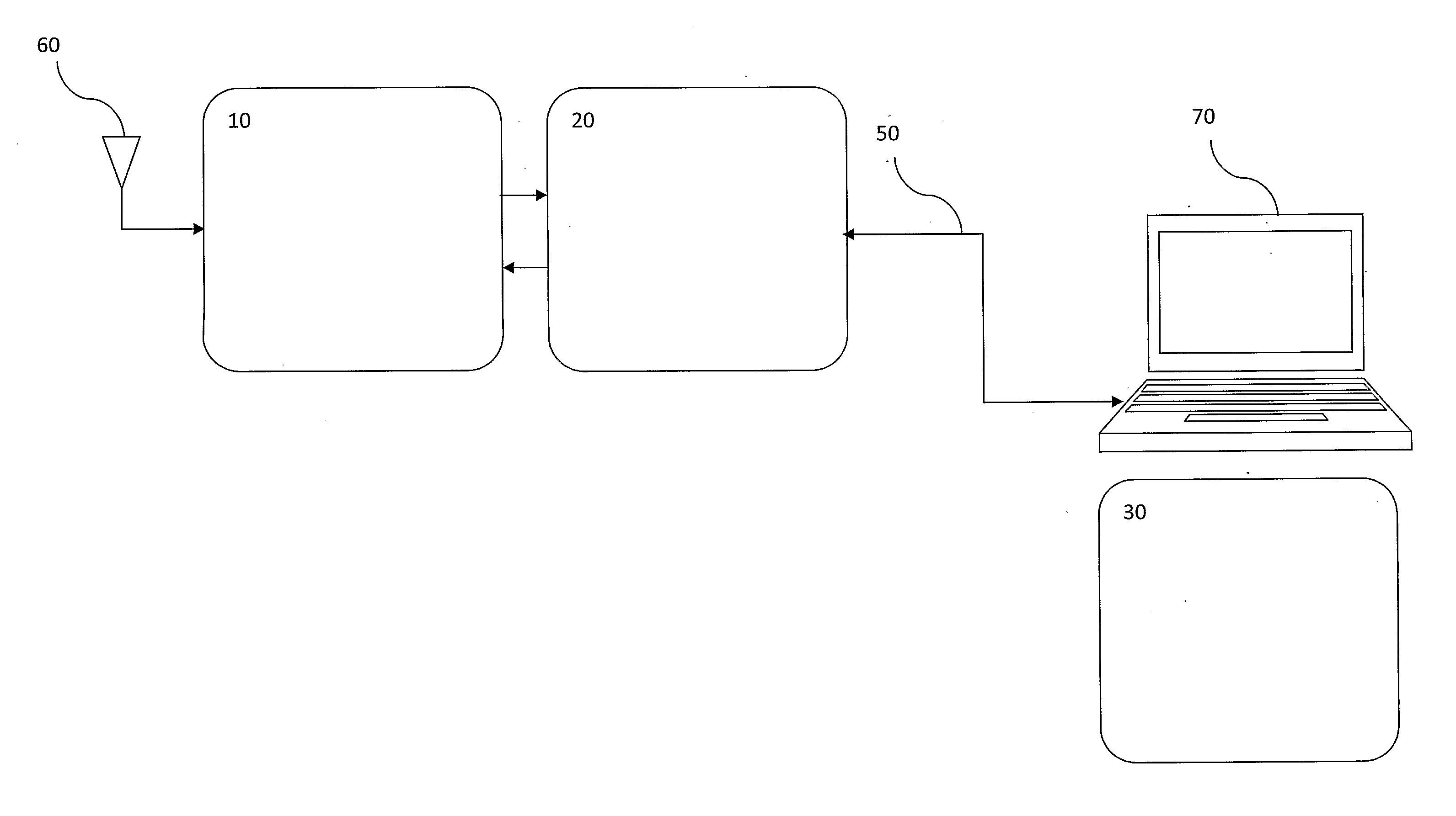
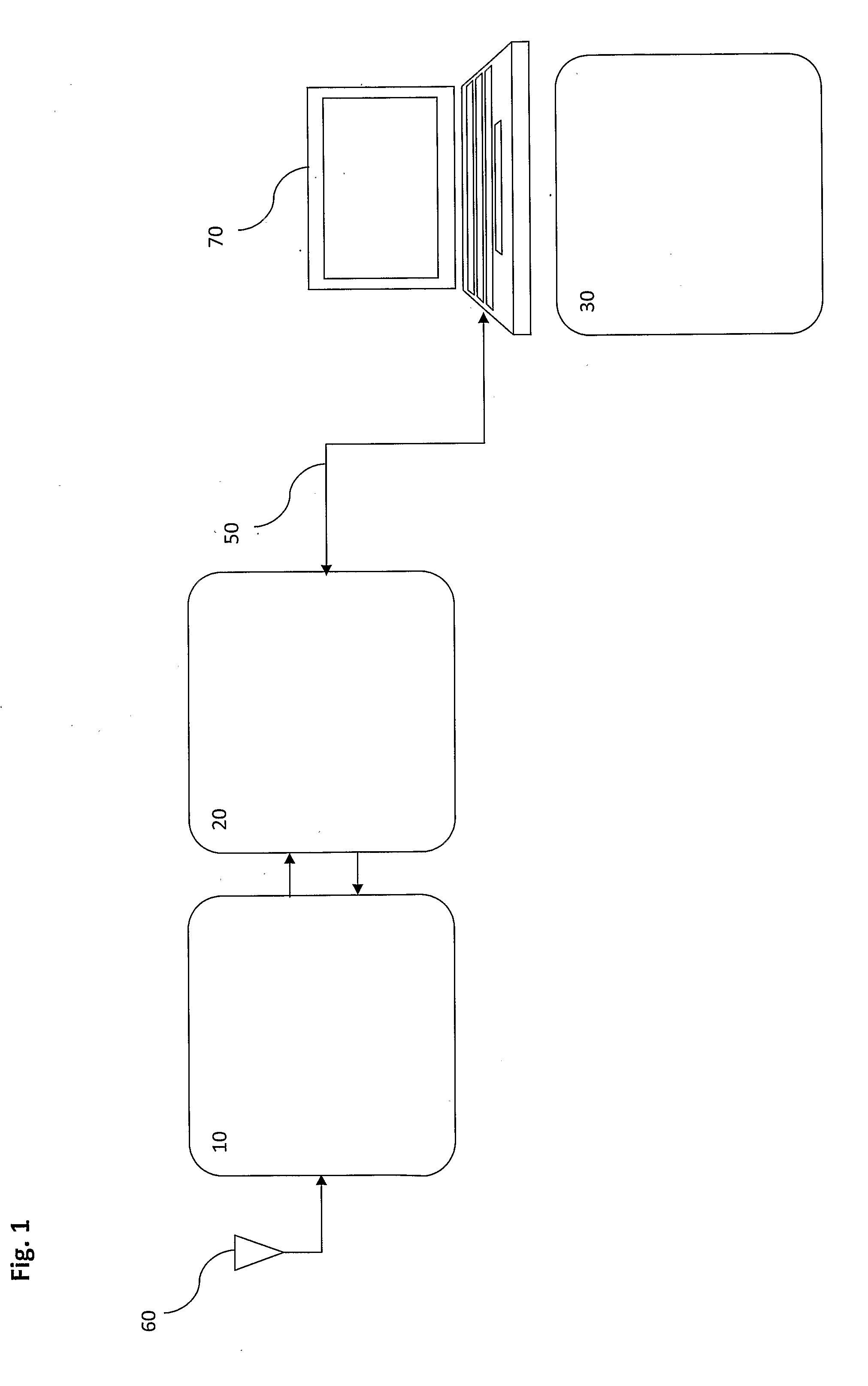
[0039]FIG. 1 shows an embodiment of a broadcast receiver system of the present invention. The broadcast receiver system comprises: a tuner 10, a tuner-to-demodulator bridge circuit (“bridge”) 20 and a software demodulator 30. The term “bridge” or “bridge circuit” as used herein should be construed to mean any circuit deployed between an analogue tuner and a demodulator. According to one embodiment, as shown in FIG. 1, the tuner 10, bridge 20 and software demodulator 30 are deployed as a modular system comprising three separate components, operably linked by suitable data connections. According to another embodiment, the tuner 10 and bridge 20 may be combined into ...


PUM


Abstract

An interface circuit configured to connect between (a) a broadcast receiver tuner and associated circuitry for the receiving and processing of broadcast radio frequency signals, and (b) a general purpose computer device programmed with software demodulation code configured to engage a general purpose processor in signal demodulation functions, the interface circuit comprising: a data interface comprising a packetisation buffer connected to receive (i) digital signal sample data from a signal path of the tuner and associated circuitry and (ii) indications of control settings which are applied to one or more configurable components during taking of the sample data, said packetisation buffer being operable to construct packets comprising blocks of sample data and header information carrying said control settings indications; a control interface configured to receive control instructions from tuner control code running on the general purpose computer device; and a microcontroller operable to receive the control instructions from the control interface and distribute corresponding control settings to configurable components of the tuner and associated circuitry, said microcontroller also being operable to supply indications of relevant control settings to said packetisation buffer.

Description

FIELD OF THE INVENTION[0001]The present invention relates generally to broadcast receivers. More particularly, the various embodiments of the present invention relate to apparatus and methods suitable for receiving digital radio and television broadcasts on all known frequencies and standards, examples of which include DAB, DVB and ATSC.BACKGROUND OF THE INVENTION[0002]Television (TV) and radio is a now ubiquitous telecommunication medium used for broadcasting and receiving images and / or sound using radio frequency (RF) signals. All televisions and radios utilise a receiver system in one form or another. A receiver is an electronic circuit that receives its input from an antenna, uses one or more filters to separate a required signal from other signals picked up by the antenna, amplifies the required signal to an amplitude suitable for further processing, and finally demodulates and decodes the signal into a consumable form for the end user, e.g. sound, pictures, digital data, etc.[...

Claims


Application Information

Patent Timeline
Patent Type & Authority Applications(United States)
IPC IPC(8): H04H40/00H04L12/26H04N5/455H04N5/44
CPCG06F11/0757H04N21/414H04N5/4401H04N21/426G06F13/102H04N5/46H04N7/0102
Inventor AHLUWALIA, KEITHATKINSON, SIMONBUDIN, DANEATON, ANTHONY
Owner MIRICS SEMICON
Why Eureka
Try Eureka