Spiral Microchannel Particle Separators, Straight Microchannel Particle Separators, and Continuous Particle Separator and Detector Systems

a technology of spiral microchannel and particle separator, which is applied in the direction of separation process, instruments, laboratory glassware, etc., can solve the problems of high cost, inefficient separation of a wide range of particles, and low detection efficiency, and achieve the effect of reducing the number of microchannels and separating particles

Active Publication Date: 2011-04-28
UNIVERSITY OF CINCINNATI
View PDF1 Cites 110 Cited by
  • Summary
  • Abstract
  • Description
  • Claims
  • Application Information

AI Technical Summary

Problems solved by technology

Traditional methods for separation and removal of microparticles from solutions involve the use of a membrane filter, which are typically limited by the membrane pore size, making them inefficient for separating a wide range of particles.
Clogging and high costs associated with membrane-based filtration on the microscale have resulted in the development of a number of membrane-less separation techniques.
However, microscale membrane-less separation techniques are not an attractive choice for filtering and separating particles in large sample volumes (˜mL) due to long analysis times. In addition, the external force fields requ

Method used


Image

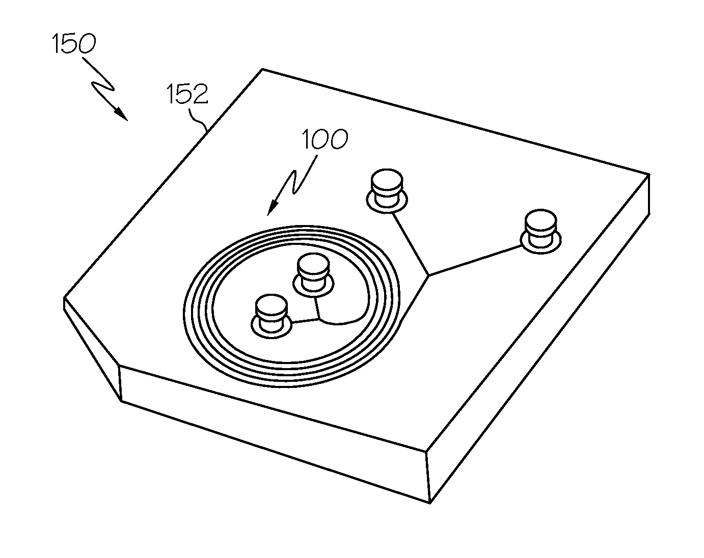
  • Spiral Microchannel Particle Separators, Straight Microchannel Particle Separators, and Continuous Particle Separator and Detector Systems
  • Spiral Microchannel Particle Separators, Straight Microchannel Particle Separators, and Continuous Particle Separator and Detector Systems
  • Spiral Microchannel Particle Separators, Straight Microchannel Particle Separators, and Continuous Particle Separator and Detector Systems

Examples


Embodiment Construction

iments described and illustrated herein;

[0045]FIG. 19B graphically depicts distribution of 780 nm diameter particles across a width of a 10×20 μm2 straight microchannel according to one or more embodiments described and illustrated herein;

[0046]FIG. 20 graphically depicts normalized particle distribution in three outlets of a 1.9 μm and 590 nm particle mixture according to one or more embodiments described and illustrated herein;

[0047]FIG. 21 graphically depicts experimental results of Rep as a function of ap / LC according to one or more embodiments described and illustrated herein;

[0048]FIG. 12 schematically depicts a top view of a straight microchannel particle separator according to one or more embodiments described and illustrated herein;

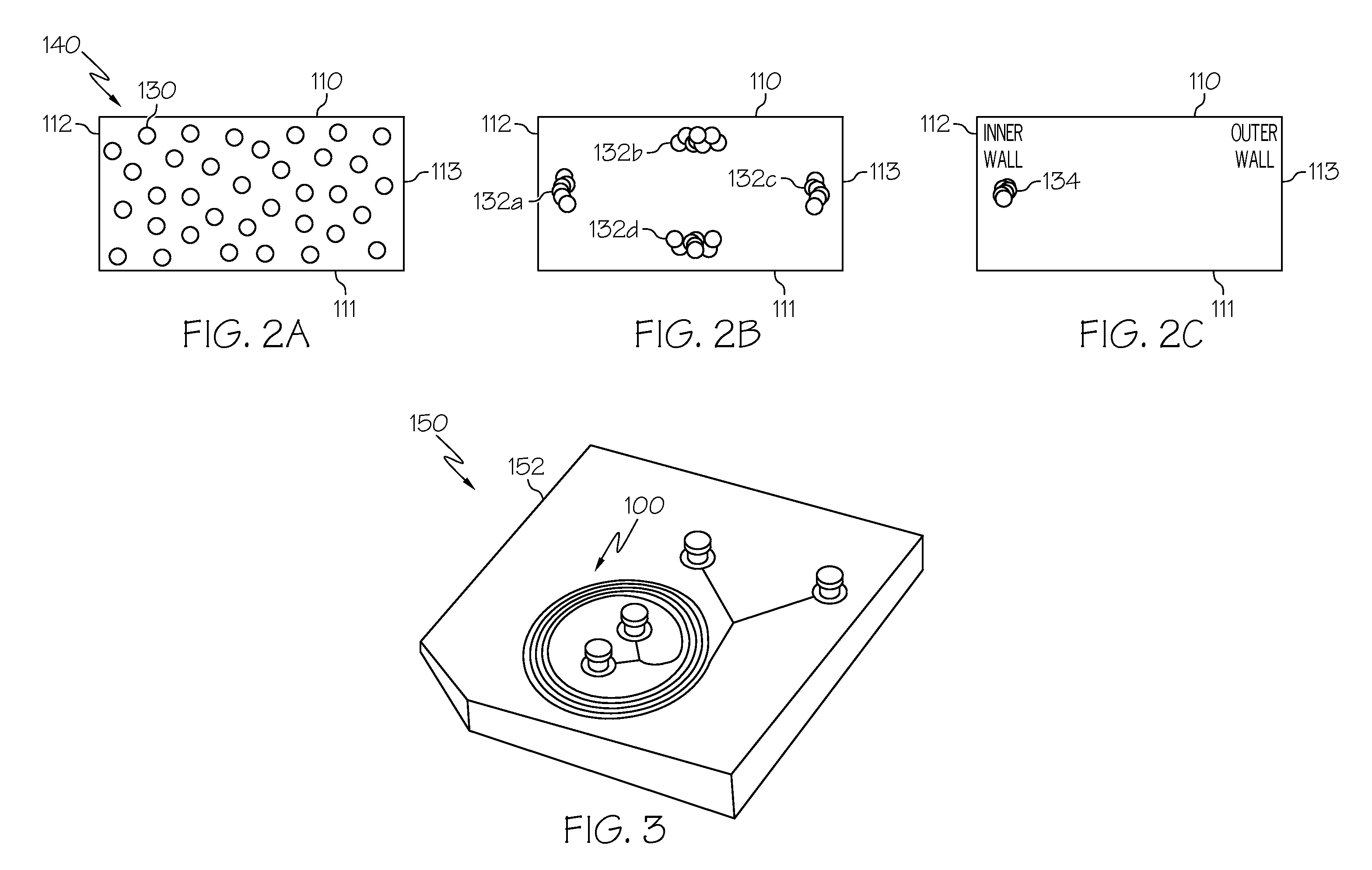
[0049]FIGS. 23A-23C schematically depict particle streams at an inlet, straight rectangular microchannel, and outlets, respectively according to one or more embodiments described and illustrated herein;

[0050]FIG. 24 graphically depicts distributi...


PUM

PropertyMeasurementUnit
Timeaaaaaaaaaa
Sizeaaaaaaaaaa
Widthaaaaaaaaaa

Abstract

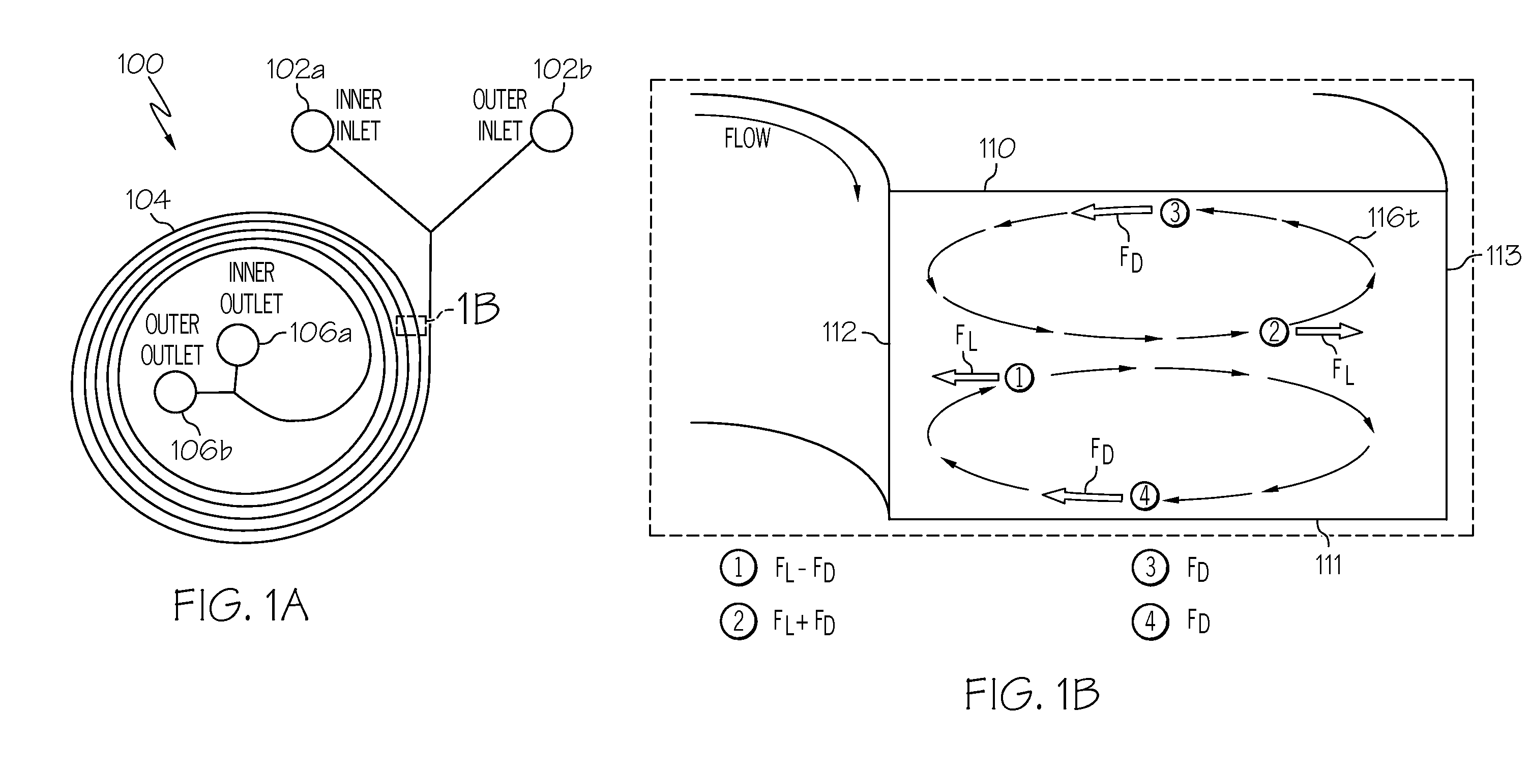
A spiral microchannel particle separator includes an inlet for receiving a solution containing particles, at least two outlets, and a microchannel arranged in a plurality of loops. Particles within a solution flowing through the spiral microchannel experience a lift force FL and a Dean drag force FD. The spiral radius of curvature R and the hydraulic diameter Dh of the spiral microchannel are such that for a flow rate U of the solution, the lift force FL and a Dean drag force FD are approximately equal and act in opposite directions for particles of a first size. The particles of the first size are focused in a single stream located at an equilibrium position near an inner wall of the microchannel. In another embodiment, a straight microchannel particle separator separates particles by modulating shear rates via high aspect ratios that focuses particles of a first size along two first walls.

Description

CROSS-REFERENCE TO RELATED APPLICATIONS[0001]The present application claims priority to U.S. Provisional Application No. 61 / 245,518, filed Sep. 24, 2009, entitled “Microfluidic Devices for Separation of Nanoparticles,” which is hereby incorporated by reference in its entirety.TECHNICAL FIELD[0002]The present specification generally relates to the separation of particles within a homogeneous solution and, more particularly, to continuous spiral and straight microchannel particle separators as well as continuous particle separator and detection systems incorporating the same.BACKGROUND[0003]Separation and filtration of microparticles based on size may be important for many applications such as biochemical and environmental assays, micro / nano-manufacturing, and clinical analysis. Traditional methods for separation and removal of microparticles from solutions involve the use of a membrane filter, which are typically limited by the membrane pore size, making them inefficient for separati...

Claims


Application Information

Patent Timeline
IPC IPC(8): G01N15/02B07B7/00B03B5/00B03B5/52
CPCB01D21/0087B01D21/265B01L3/502753G01N2030/002B01L2300/0883B03B5/32G01N15/0255B01L2300/0864
Inventor PAPAUTSKY, IANBHAGAT, ALI ASGAR S.
Owner UNIVERSITY OF CINCINNATI
Why Eureka
Try Eureka