Flexible drainage cell

a drainage cell and flexible technology, applied in the field of improved drainage cells, can solve the problems of impeding water flow, geotextile tending to sag, and inability to discharge water, so as to reduce the tendency of geotextile to sag, reduce the volume occupied by drainage cells, and improve the cost-effective transport of drainage cells

Inactive Publication Date: 2011-04-28
LEE ALAN SIAN GHEE
View PDF8 Cites 25 Cited by
  • Summary
  • Abstract
  • Description
  • Claims
  • Application Information

AI Technical Summary

Benefits of technology

[0012]Advantageously, providing apertures in the side walls of the tubular structures significantly improves not only the rate of flow of the water through the cell but also creates a higher internal drain void volume area as the water can occupy the interior of the tubular structures and not just the volume between cones. This contrasts with existing drainage cells in which the interior of the conical structures is not occupied by water.
[0015]In use the drainage cell is used in the opposite orientation to existing drainage cells with the cell resting on and supported by the base of the tubular structures. The total area of the base of the tubular structures is typically less than 35%, most preferably less than 25% of the total area of the base of the cell. In one specific preferred embodiment the area is about 20%. The geo-textile layer is better supported by the planar backing layer and this reduces the tendency for the geo-textile to sag.
[0016]Because the geo-textile lies against the backing sheet and not on the ends of the tubular members, as in prior art drainage cells, it is possible for the drainage cells to be nested with the tubular structures from one drainage cell nesting in between the gaps between the tubular structures of another drainage cell. This significantly reduces the volume occupied by the drainage cells and makes transport of the drainage cells more cost effective.
[0018]Typically the holes in the sheet have a diameter of about 15 to 25 mm, most preferably about 22.5 mm, to maximise the open area of the cell without compromising its strength. The diameter at the base of the conical structures is in the order of 18.5 mm for a 22.5 mm diameter hole.
[0019]The total area of the holes in the sheet is typically around 60 to 65% of the area of the sheet. This allows for rapid drainage.

Problems solved by technology

However, the problem with the existing drainage cells is that flow tends to be inhibited by the volume of the conical dimples occupying the space beneath the geo-textile layer.
More significantly, the geo-textile tends to sag due to the weight of soil or other growth medium lying on top of the geo-textile layer.
This tends to block or partially block the spaces between the conical dimples, thus impeding water flow and slowing the rate of water flow through the drainage cell.
The problem of sagging geo-textile tends to increase as the drainage cell and geo-textile age.

Method used


Image

  • Flexible drainage cell
  • Flexible drainage cell
  • Flexible drainage cell

Examples


Embodiment Construction

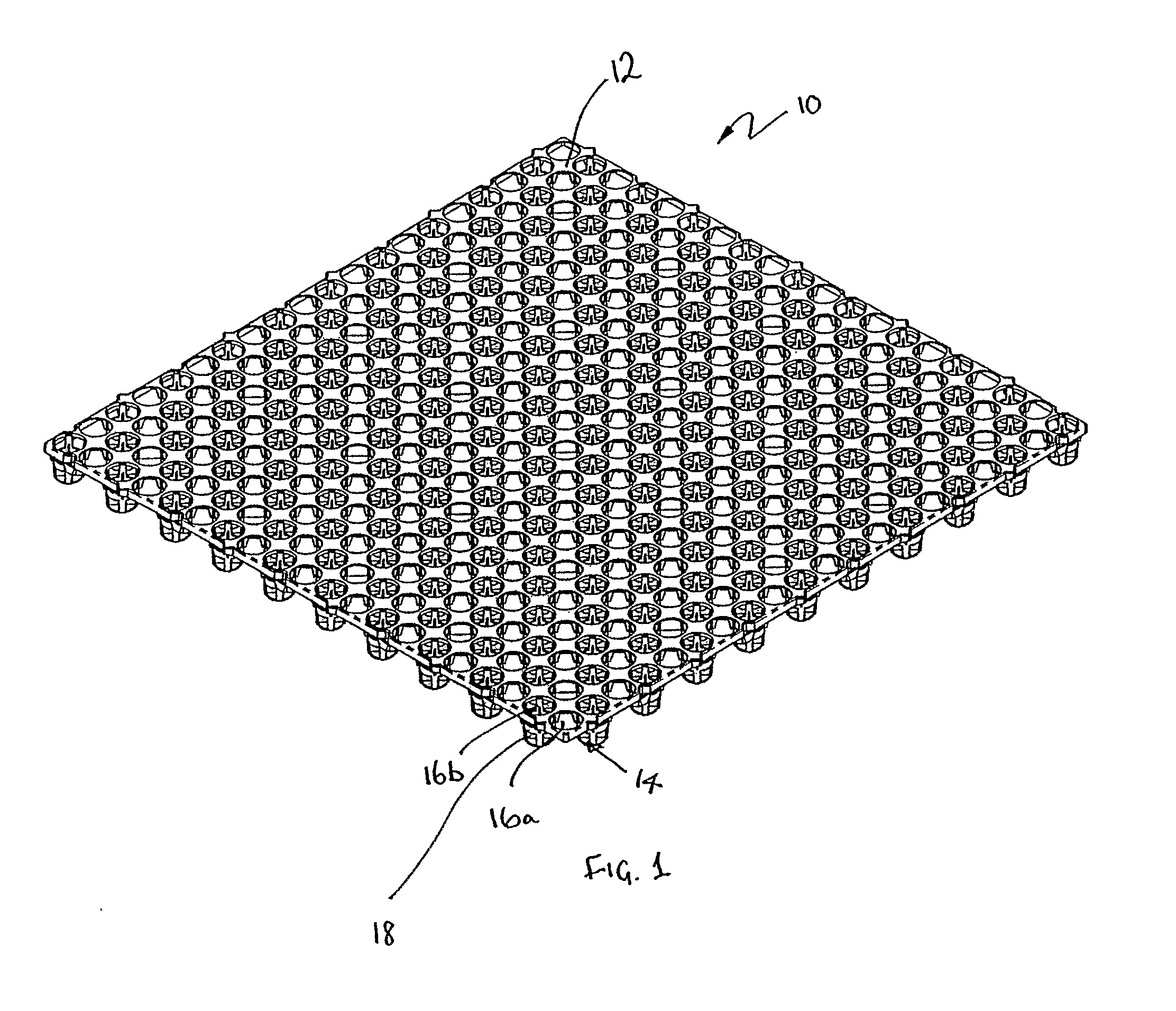
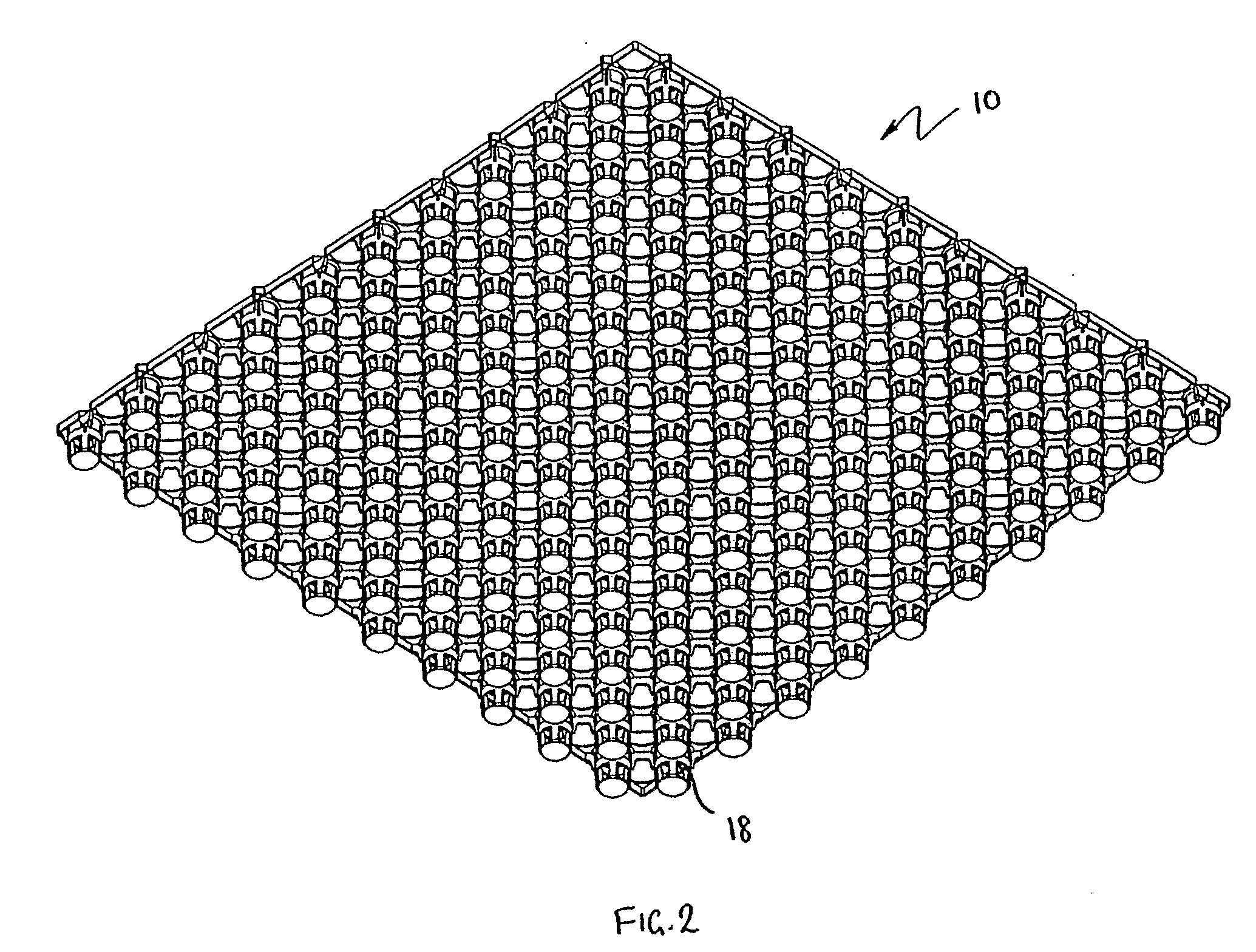
[0033]Referring to the drawings, FIGS. 1 and 2, show a drainage cell 10 embodying the present invention. The drainage cell is typically injection molded from a plastics material such as polypropylene, HDPE or LDPE. Recycled polypropylene may be used. However, any other suitable materials which can be molded or cast may be used. In the specific embodiment, the cell is about 30 mm high but it may range from 15 mm to 50 mm or more.

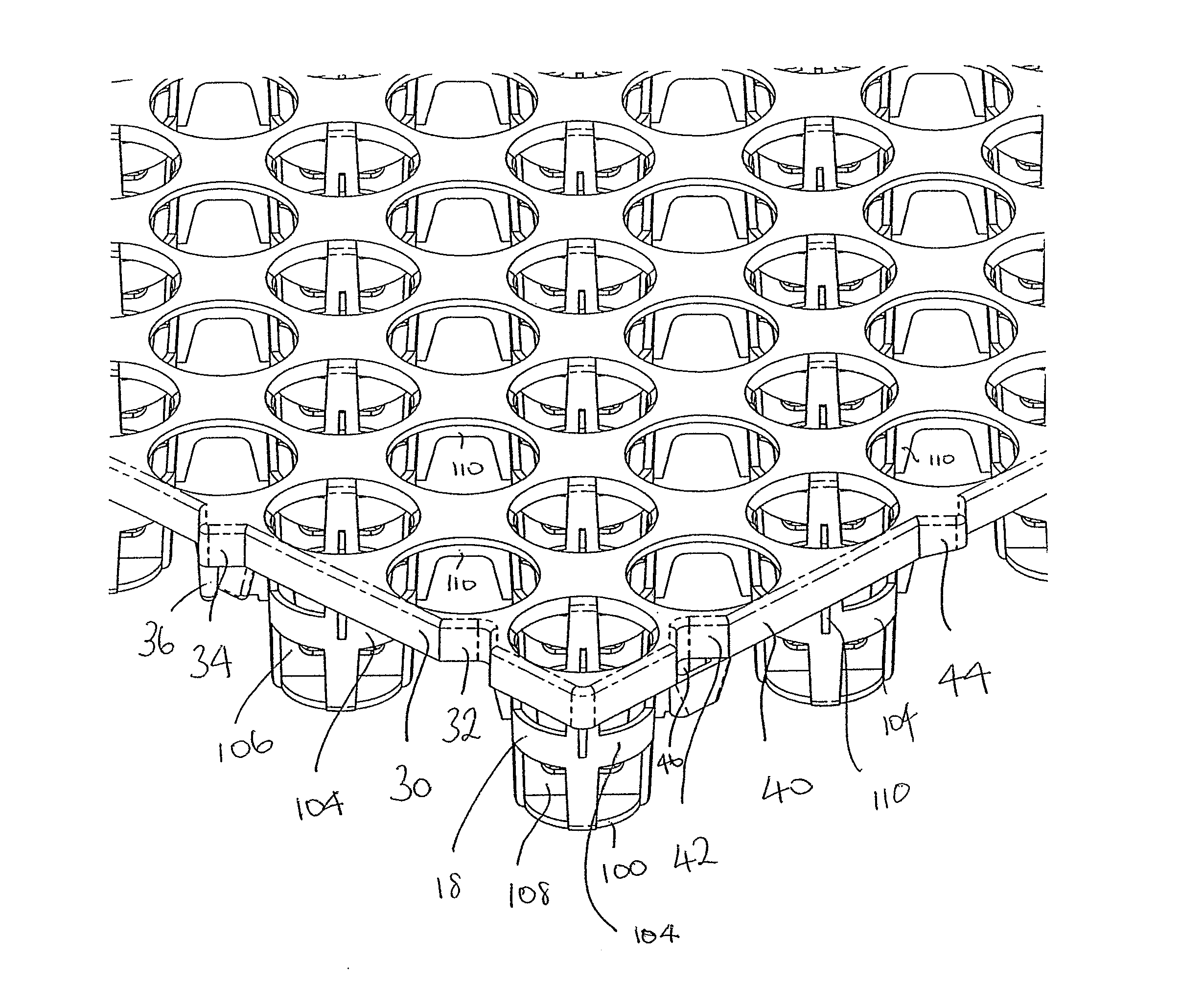
[0034]The drainage cell 10 comprises a generally square sheet of plastics material defining a perforated backing plate 12 which defines a plurality of parallel rows 14 of first and second circular holes 16a and 16b. A tubular support member 18 which is generally frusto-conical, extends from each second hole 16b.

[0035]More specifically, with reference to FIGS. 3 and 5, it can be seen that in each row 14, running parallel to the side of the cell, a support member 18 depends from every second hole 16b in the row, with unsupported holes 16a being located between...


PUM


Abstract

A drainage cell (10) comprises a backing plate (12) defining a plurality of holes (16a, 16b), a series of conical tubular structures (18) having side walls and a base extending from the backing layer, the tubular structures being in fluid communication with at least some of the holes (16a, 16b) in the backing plate (12) thereby allowing fluid to pass through the holes into a generally tubular structure. The sides of the tubular structures define apertures (109) permitting fluid flow out of the tubular structures through the walls of the tubular portions. Typically, the perforated or open area of the tubular structures is at least 20% of the area of the side walls of the tubular structures, more preferably at least 40%, more preferably 50% or greater and most preferably of the order of 70 to 75%. Providing apertures (109) in the side walls of the tubular structures significantly improves not only the rate of flow of the water through the cell but also creates a higher internal drain void volume area as the water can occupy the interior of the tubular structures and not just the volume in between the tubular structures.

Description

CROSS-REFERENCE TO RELATED APPLICATIONS[0001]This application claims priority from Australian provisional patent application No 2008902415 entitled “Flexible drainage cell” filed 16 May 2008, the entire contents of which are hereby incorporated by reference.FIELD OF THE INVENTION[0002]This invention relates to an improved drainage cell.[0003]BACKGROUND TO THE INVENTION[0004]The control and flow of surface water, such as rain water or storm water, is important in preventing the build up of surface water adjacent to the foundations of buildings or other structures, and in other areas such as playing fields, golf courses, landscaped decks, gardens and the like. Roof gardens are becoming increasingly popular both to “green” buildings and make them more environmentally friendly, and also to provide recreational spaces. The use of drainage cells in roof gardens is critical in allowing excess water to escape quickly from the roof garden to drainage outlets. This reduces the potential for l...

Claims


Application Information

Patent Timeline
Patent Type & Authority Applications(United States)
IPC IPC(8): E02B11/00
CPCE01C13/083E02B11/00E02D17/20E01C3/06Y02B80/32E01C3/006E04D11/002Y02A30/254
Inventor LEE, ALAN SIAN GHEEOLIVER, DAVIDGREAVES, HENRY
Owner LEE ALAN SIAN GHEE
Why Eureka
Try Eureka