Fluid conveyance system including flexible retaining mechanism

a technology of fluid conveyance and flexible retaining mechanism, which is applied in the direction of mechanical equipment, transportation and packaging, machines/engines, etc., can solve the problems of large amount of chemical vapor deposition reaction, difficult to avoid some direct reaction of different precursors, and relatively insensitive to transport non-uniformities, so as to minimize the time of an ald reaction, maximize the flux of chemicals flowing, and maximize the effect of chemical flux

Inactive Publication Date: 2011-04-28
EASTMAN KODAK CO
View PDF19 Cites 45 Cited by
  • Summary
  • Abstract
  • Description
  • Claims
  • Application Information

AI Technical Summary

Benefits of technology

[0023]In an effort to minimize the time that an ALD reaction needs to reach self-termination, at any given reaction temperature, one approach has been to maximize the flux of chemicals flowing into the ALD reactor, using so-called “pulsing” systems. In order to maximize the flux of chemicals into the ALD reactor, it is advantageous to introduce the molecular precursors into the ALD reactor with minimum dilution of inert gas and at high pressures. However, these measures work against the need to achieve short cycle times and the rapid removal of these molecular precursors from the ALD reactor. Rapid removal in turn dictates that gas residence time in the ALD reactor be minimized. Gas residence times, τ, are proportional to the volume of the reactor, V, the pressure, P, in the ALD reactor, and the inverse of the flow, Q, that is:
[0024]In a typical ALD chamber the volume (V) and pressure (P) are dictated independently by the mechanical and pumping constraints, leading to difficulty in precisely controlling the residence time to low values. Accordingly, lowering pressure (P) in the ALD reactor facilitates low gas residence times and increases the speed of removal (purge) of chemical precursor from the ALD reactor. In contrast, minimizing the ALD reaction time requires maximizing the flux of chemical precursors into the ALD reactor through the use of a high pressure within the ALD reactor. In addition, both gas residence time and chemical usage efficiency are inversely proportional to the flow. Thus, while lowering flow can increase efficiency, it also increases gas residence time.

Problems solved by technology

In practice, in any system it is difficult to avoid some direct reaction of the different precursors leading to a small amount of chemical vapor deposition reaction.
Self-saturating surface reactions make ALD relatively insensitive to transport non-uniformities, which might otherwise impair surface uniformity, due to engineering tolerances and the limitations of the flow system or related to surface topography (that is, deposition into three dimensional, high aspect ratio structures).
As a general rule, a non-uniform flux of chemicals in a reactive process generally results in different completion times over different portions of the surface area.
However, in spite of its inherent technical capabilities and advantages, a number of technical hurdles still remain.
However, it is difficult to obtain a reliable scheme for introducing the needed series of gaseous formulations into a chamber at the needed speeds and without some unwanted mixing.
In a typical ALD chamber the volume (V) and pressure (P) are dictated independently by the mechanical and pumping constraints, leading to difficulty in precisely controlling the residence time to low values.
Existing ALD approaches have been compromised with the trade-off between the need to shorten reaction times with improved chemical utilization efficiency, and, on the other hand, the need to minimize purge-gas residence and chemical removal times. One approach to overcome the inherent limitations of “pulsed” delivery of gaseous material is to provide each reactant gas continuously and to move the substrate through each gas in succession.
While systems such as those described in the '563 Yudovsky and '022 Suntola et al. patents may avoid some of the difficulties inherent to pulsed gas approaches, these systems have other drawbacks.
The complex arrangements of both the gas flow delivery unit of the '563 Yudovsky patent and the gas flow array of the '022 Suntola et al. patent, each providing both gas flow and vacuum, make these solutions difficult to implement, costly to scale, and limit their potential usability to deposition applications onto a moving substrate of limited dimensions.
Moreover, it would be very difficult to maintain a uniform vacuum at different points in an array and to maintain synchronous gas flow and vacuum at complementary pressures, thus compromising the uniformity of gas flux that is provided to the substrate surface.

Method used


Image

  • Fluid conveyance system including flexible retaining mechanism
  • Fluid conveyance system including flexible retaining mechanism
  • Fluid conveyance system including flexible retaining mechanism

Examples


Embodiment Construction

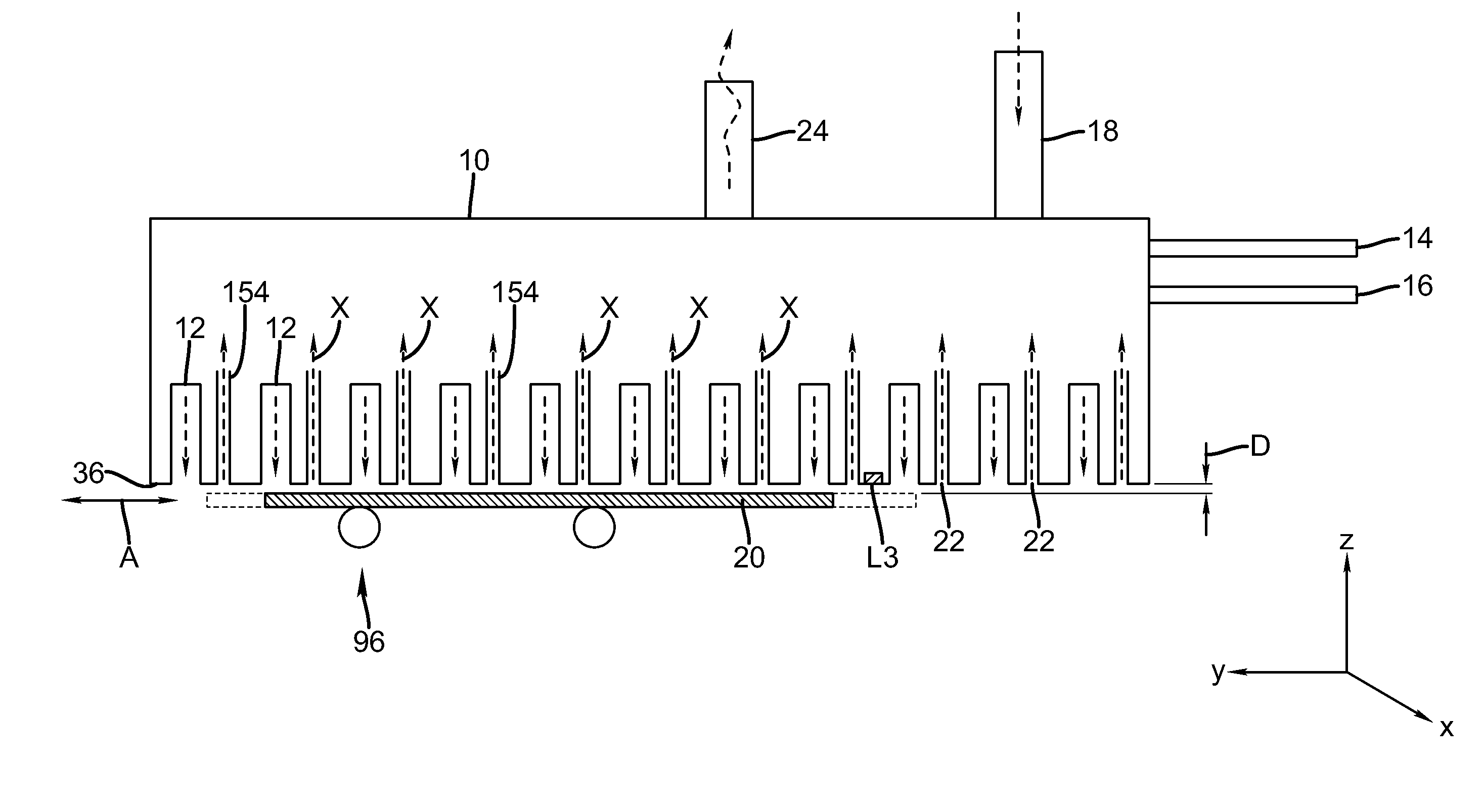
[0083]The present description will be directed in particular to elements forming part of, or cooperating more directly with, apparatus in accordance with the present invention. It is to be understood that elements not specifically shown or described can take various forms well known to those skilled in the art. In the following description and drawings, identical reference numerals have been used, where possible, to designate identical elements.

[0084]The example embodiments of the present invention are illustrated schematically and not to scale for the sake of clarity. The figures provided are intended to show overall function and the structural arrangement of the example embodiments of the present invention. One of the ordinary skills in the art will be able to readily determine the specific size and interconnections of the elements of the example embodiments of the present invention.

[0085]For the description that follows, the term “gas” or “gaseous material” is used in a broad sen...


PUM

PropertyMeasurementUnit
mechanical pressureaaaaaaaaaa
pressureaaaaaaaaaa
flexibleaaaaaaaaaa

Abstract

A fluid conveyance system for thin film material deposition includes a fluid distribution manifold and a substrate transport mechanism. The fluid distribution manifold includes an output face that includes a plurality of elongated slots. The output face of the fluid distribution manifold is positioned opposite a first surface of the substrate such that the elongated slots face the first surface of the substrate and are positioned proximate to the first surface of the substrate. The substrate transport mechanism causes a substrate to travel in a direction and includes a flexible mechanism that contacts a second surface of the substrate in a region that is proximate to the output face of the fluid distribution manifold.

Description

CROSS REFERENCE TO RELATED APPLICATIONS[0001]Reference is made to commonly-assigned, U.S. patent application Ser. No. ______ (Docket 95866), entitled “FLUID DISTRIBUTION MANIFOLD INCLUDING BONDED PLATES”, Ser. No. ______ (Docket 95868), entitled “FLUID DISTRIBUTION MANIFOLD INCLUDING MIRRORED FINISH PLATE”, Ser. No. ______ (Docket 95869), entitled “DISTRIBUTION MANIFOLD INCLUDING MULTIPLE FLUID COMMUNICATION PORTS”, Ser. No. ______ (Docket 95870), entitled “FLUID DISTRIBUTION MANIFOLD INCLUDING NON-PARALLEL NON-PERPENDICULAR SLOTS”, Ser. No. ______ (Docket 95871), entitled “FLUID DISTRIBUTION MANIFOLD INCLUDING COMPLIANT PLATES”, Ser. No. ______ (Docket 95873), entitled “CONVEYANCE SYSTEM INCLUDING OPPOSED FLUID DISTRIBUTION MANIFOLDS” Ser. No. ______ (Docket 95874), entitled “FLUID DISTRIBUTION MANIFOLD OPERATING STATE MANAGEMENT SYSTEM”, all filed concurrently herewith.FIELD OF THE INVENTION[0002]This invention generally relates diffusing flow of a gaseous or liquid material, espe...

Claims


Application Information

Patent Timeline
Patent Type & Authority Applications(United States)
IPC IPC(8): C23C16/458C23C16/00
CPCC23C16/45551C23C16/545C23C16/458Y10T137/8593
Inventor KERR, ROGER S.LEVY, DAVID H.SUTTON, JAMES E.
Owner EASTMAN KODAK CO
Why Eureka
Try Eureka