Phototherapy Device Thermal Control Apparatus and Method

a technology of thermal control apparatus and phototherapy device, which is applied in the field of thermal control apparatus and method, can solve the problems of discharging heat into, affecting the efficiency of phototherapy devices, so as to reduce or eliminate the problems or disadvantages associated with them

Active Publication Date: 2011-04-28
CHANNEL INVESTMENTS LLC
View PDF6 Cites 20 Cited by
  • Summary
  • Abstract
  • Description
  • Claims
  • Application Information

AI Technical Summary

Benefits of technology

[0006]Particular embodiments of the present invention may reduce or eliminate problems or disadvantages associated with phototherapy device operation.

Problems solved by technology

In addition, during operation a phototherapy device may be subjected to external heat loads or heat sinks that involve the transfer of heat to the phototherapy device (i.e., external heat load) or from the phototherapy device (i.e., an external heat sink).
Also, by way of further example, a phototherapy device comprising a dermatologic device may dissipate heat into the air of the room in which this device is used.
A problem associated with phototherapy devices, then, involves the control and management of heat sinks and heat loads, both internal and external to the device, including without limitation the control and management of heat transfer between one or more of such heat sinks, heat loads, and the device, to promote efficient and enhanced device operation and performance.

Method used


Image

  • Phototherapy Device Thermal Control Apparatus and Method
  • Phototherapy Device Thermal Control Apparatus and Method
  • Phototherapy Device Thermal Control Apparatus and Method

Examples


example 1

[0097]Initial pulse repetition frequency is one light pulse every two seconds. The device detects that a thermal limit threshold has been reached (e.g., sensed device tip temperature reaches a set point of approximately 37° C.). The pulse repetition frequency is then reduced to one light pulse every 2.5 seconds until either the condition is alleviated (e.g., tip temperature drops below the 37° C. set point) or a second thermal trigger is reached (e.g., tip temperature drops to a specified level). At such time, pulse repetition frequency is increased to greater than one light pulse every 2.5 seconds.

example 2

[0098]Initial pulse repetition frequency is one light pulse every two seconds. The device detects that a thermal limit may be reached (e.g., sensed device tip temperature is increasing toward or is near approximately 37° C.). The pulse repetition frequency is then reduced, or device operation suspended, as necessary to avoid establishment of the thermal limit condition. When a lower thermal trigger of 34° C. is sensed, pulse repetition frequency is increased again to one light pulse every two seconds.

[0099]Laser diode bars typically may be about 50% efficient at normal baseline operating temperatures. Thus, by way of example, for a laser diode bar at 25° C., a forty watt (40 W) electrical input results in about a twenty watt (20 W) optical output and a twenty watt (20 W) thermal output. At higher temperatures, though, laser diode bars are less efficient. For example, for a laser diode bar at 42° C., a forty watt (40 W) electrical input produces a sixteen watt (16 W) optical output a...


PUM


Abstract

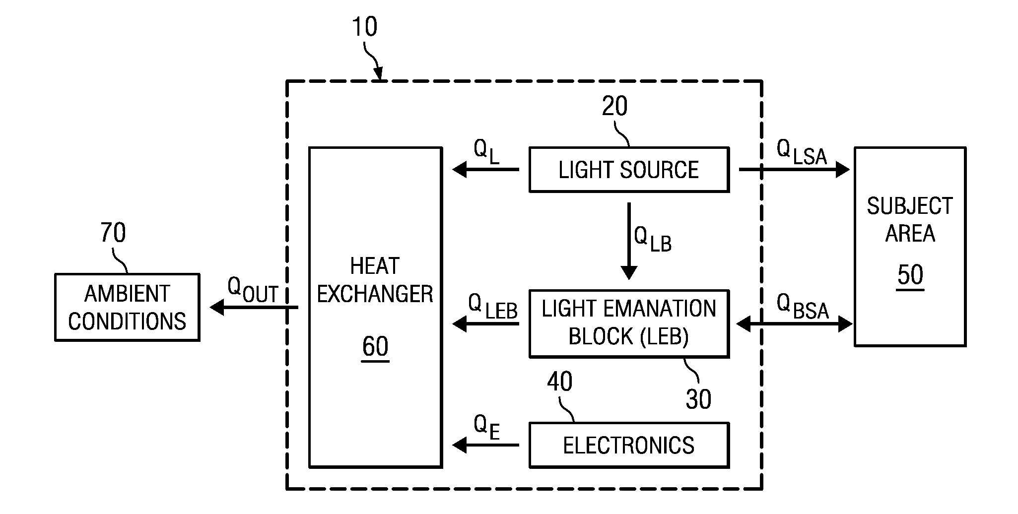
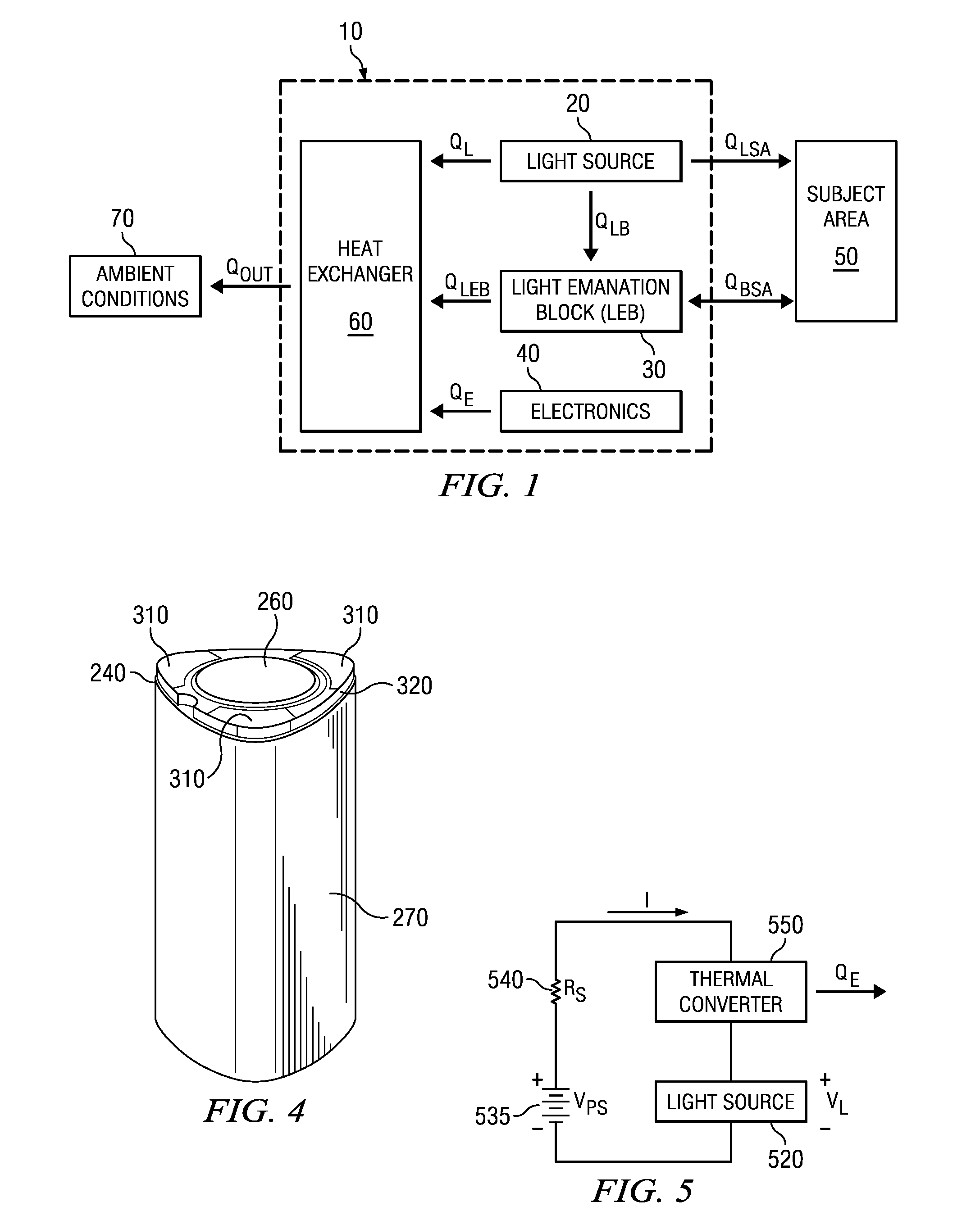
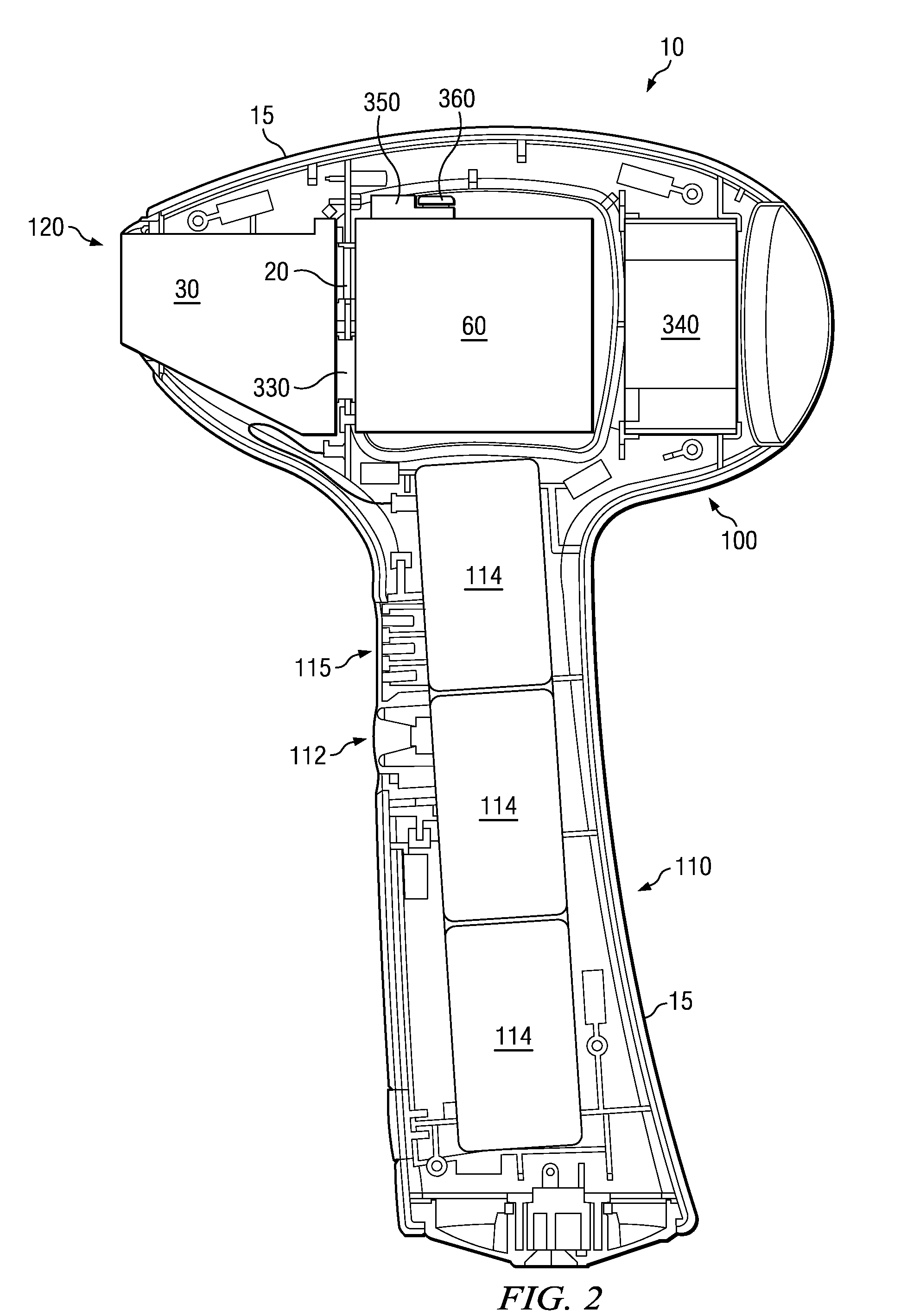
A phototherapy device includes a light source; a light emanation block; and a heat exchanger for the dissipation of heat from one or more heat loads associated with the device. Heat may be transferred via the heat exchanger from the light source independently of the dissipation of heat from one or more of the other device heat loads. Substantially thermally isolated heat transfer regions may be provided, and such regions may be maintained at different operating temperatures, to control the transfer of heat in conjunction with a phototherapy method and to promote efficient and enhanced device operation and performance.

Description

TECHNICAL FIELD[0001]The invention relates generally to a thermal control apparatus and method, and more particularly, in accordance with one range of embodiments, to an apparatus and method for controlling the transfer of heat in a phototherapy device.BACKGROUND[0002]A phototherapy device is an apparatus that includes one or more sources of light energy. A phototherapy device typically generates light energy for a particular desired purpose. For example, a phototherapy device may comprise a dermatologic device that generates light energy for application to skin, e.g., for hair removal, acne treatment, tattoo removal, etc.[0003]The operation of a phototherapy device generally involves, among other things, the generation of heat by the device. Such heat generation typically involves the production of multiple heat loads within the phototherapy device. By way of example, the phototherapy device light source produces heat. Also, the phototherapy device electronics (e.g., power supply, ...

Claims


Application Information

Patent Timeline
Patent Type & Authority Applications(United States)
IPC IPC(8): A61N5/06
CPCA61B18/203A61N2005/067A61B2017/00769A61B2018/00005A61B2018/00452A61B2018/00476A61B2018/2261A61B2019/465A61N5/0616A61N2005/005A61N2005/063A61N2005/0644A61N2005/0651A61N2005/0659A61N2005/0661A61N2005/0662A61B2017/00026A61B2090/065A61N5/067
Inventor WECKWERTH, MARK V.SCHUETZ, CHARLES A.LIU, HARVEY I.REICHERT, PATRICKISLAND, TOBIN C.GROVE, ROBERT E.
Owner CHANNEL INVESTMENTS LLC
Why Eureka
Try Eureka