Control device for legged mobile robot

Active Publication Date: 2011-04-28
HONDA MOTOR CO LTD
View PDF13 Cites 52 Cited by
  • Summary
  • Abstract
  • Description
  • Claims
  • Application Information

AI Technical Summary

Benefits of technology

[0014]The present invention has been made with a view of the background described above, and it is an object of the invention to provide a control device capable of controlling the motion of a robot

Problems solved by technology

As a result, a motion of a desired gait that makes it difficult for the

Method used


Image

  • Control device for legged mobile robot
  • Control device for legged mobile robot
  • Control device for legged mobile robot

Examples


Embodiment Construction

[0068]The following will describe an embodiment of the present invention by taking a bipedal mobile robot as an example of a legged mobile robot.

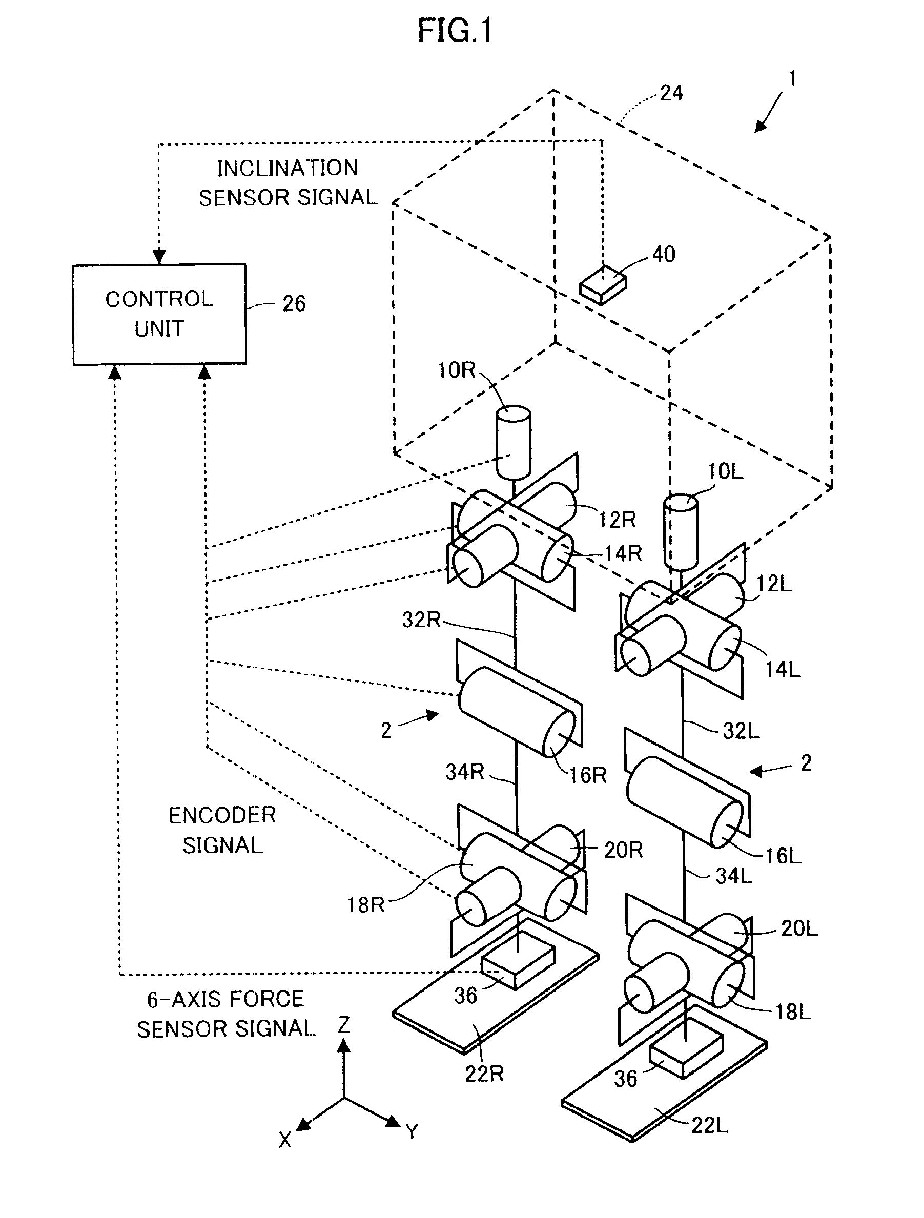
[0069]As illustrated in FIG. 1, a bipedal mobile robot 1 (hereinafter referred to simply as the robot 1 according to the present embodiment has a body 24 as a base body and a pair of right and left legs (leg links) 2, 2 extended from the body 24 as a moving mechanism for moving the body 24 above a floor surface.

[0070]The body 24 is connected to the proximal end portions (upper end portions) of the two legs 2, 2 through the intermediary of a waist joint (hip joint), which will be discussed later, and is supported above the floor surface by one or both of the legs 2, 2 that are in contact with the ground.

[0071]The two legs 2, 2 share the same construction and each thereof has six joints. The six joints are a joint 10R or 10L for turning a waist (hip) (for the rotation in the yaw direction relative to the body 24), a joint 12R or 12L for turni...


PUM


Abstract

A control device for a legged mobile robot has a unit which generates the time series of a future predicted value of a model external force manipulated variable as a feedback manipulated variable for reducing the deviation of the posture of the robot. A desired motion determining unit sequentially determines the instantaneous value of a desired motion such that the motion of the robot will reach or converge to a reaching target in the future in the case where it is assumed that the time series of an additional external force defined by the time series of a future predicted value of the model external force manipulated variable is additionally applied to the robot on a dynamic model.

Description

BACKGROUND OF THE INVENTION[0001]1. Field of the Invention[0002]The present invention relates to a control device for a legged mobile robot, such as a bipedal robot.[0003]2. Description of the Related Art[0004]As a technique for enhancing the stability of the posture of a legged mobile robot, which travels by moving a plurality of legs extended from a base body, the technique disclosed in, for example, Japanese Patent No. 3269852 has been proposed by the applicant of the present application.[0005]According to the technique, a state amount deviation of an actual posture of the body of a robot from a desired posture is observed, and an operational moment (an operational moment about a desired ZMP) to be additionally applied to the robot is calculated according to a PD law (proportional-differential law) from the observed value of the state amount deviation as the feedback manipulated variable (control input) required to converge the state amount deviation to zero.[0006]Further, the op...

Claims


Application Information

Patent Timeline
IPC IPC(8): B25J13/00
CPCB62D57/032
Inventor YOSHIIKE, TAKAHIDEKANEKO, HIROYUKIORITA, ATSUO
Owner HONDA MOTOR CO LTD
Why Eureka
Try Eureka