
Dynamic graphical user interface layout

a graphical user interface and layout technology, applied in the direction of instruments, computing, electric digital data processing, etc., can solve the problems of not properly adjusting one or more of the gui elements, affecting the design and specification of the graphical user interface by the developer, and affecting the development of the gui

Inactive Publication Date: 2011-04-28
MICROSOFT TECH LICENSING LLC
View PDF27 Cites 48 Cited by
  • Summary
  • Abstract
  • Description
  • Claims
  • Application Information

AI Technical Summary

Benefits of technology

This Summary is provided to introduce a selection of concepts in a simplified form that are further described below in the Detailed Description. This Summary is n...

Problems solved by technology

The design and specification of a graphical user interface by a developer can be a complex task.
Development of a GUI is subject to errors of not accounting for one or more environments.
An example of this is a GUI that may be correct when a window is a normal size, but one or more of the GUI elements does not adjust properly when the window is maximized.

Method used


Image

  • Dynamic graphical user interface layout
  • Dynamic graphical user interface layout
  • Dynamic graphical user interface layout

Examples


example environment 100

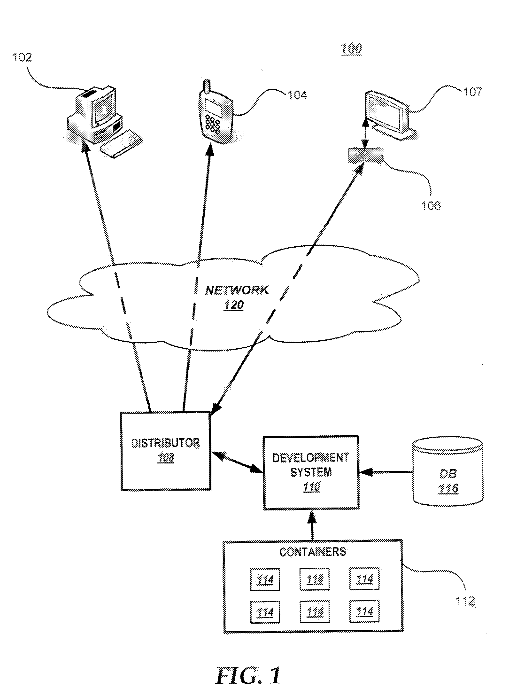
Example environment 100 includes distributor 108. Distributor 108 may be a computing device, server, or a server farm that includes multiple servers, or a process executing thereon. Distributor 108 may include a Web server, an FTP server, or other type of server. Distributor 108 may be a network file share in a local area network or another type of network. Distributor 108 may store files or other data for installation on one or more of clients 102-106. Distributor 108 may receive a request to install or update an application residing on one of clients 102-106 and, in response, perform actions to facilitate the installation or update, such as downloading files to the client. Distributor 108 may include a Web server or other type of server that provides programs, Web pages, files, or data to clients 102-106.

In the illustrated example environment, distributor 108 communicates with development system 110. Development system 110 may be one or more client computing devices, one or more s...

example form 302

Example form 302 includes a number of GUI elements. It includes “Customers” label 304, list box 310, buttons 312, “Name” label 330, text box 332, “Address” label 334, text box 336, “Phone” label 338, text box 340, “Orders” label 344, and grid 346. Some of these elements may be grouped and referred to as child elements of a parent control or container. In one embodiment, “Customers” label 304, list box 310, and buttons 312 are child elements of list control 308. List control 308 is represented by a dotted line enclosing its child elements, though the dotted line may not be visible in the GUI. Similarly “Orders” label 344 and grid 346 may be grouped together as child elements of grid control 342.

As illustrated by FIG. 3, one or more GUI components may be included within a container. In one embodiment, a container corresponds to a region of a form. In FIG. 3, dashed lines are used to illustrate a container and its corresponding region. As illustrated, sizing container 320 includes text...


PUM


Abstract

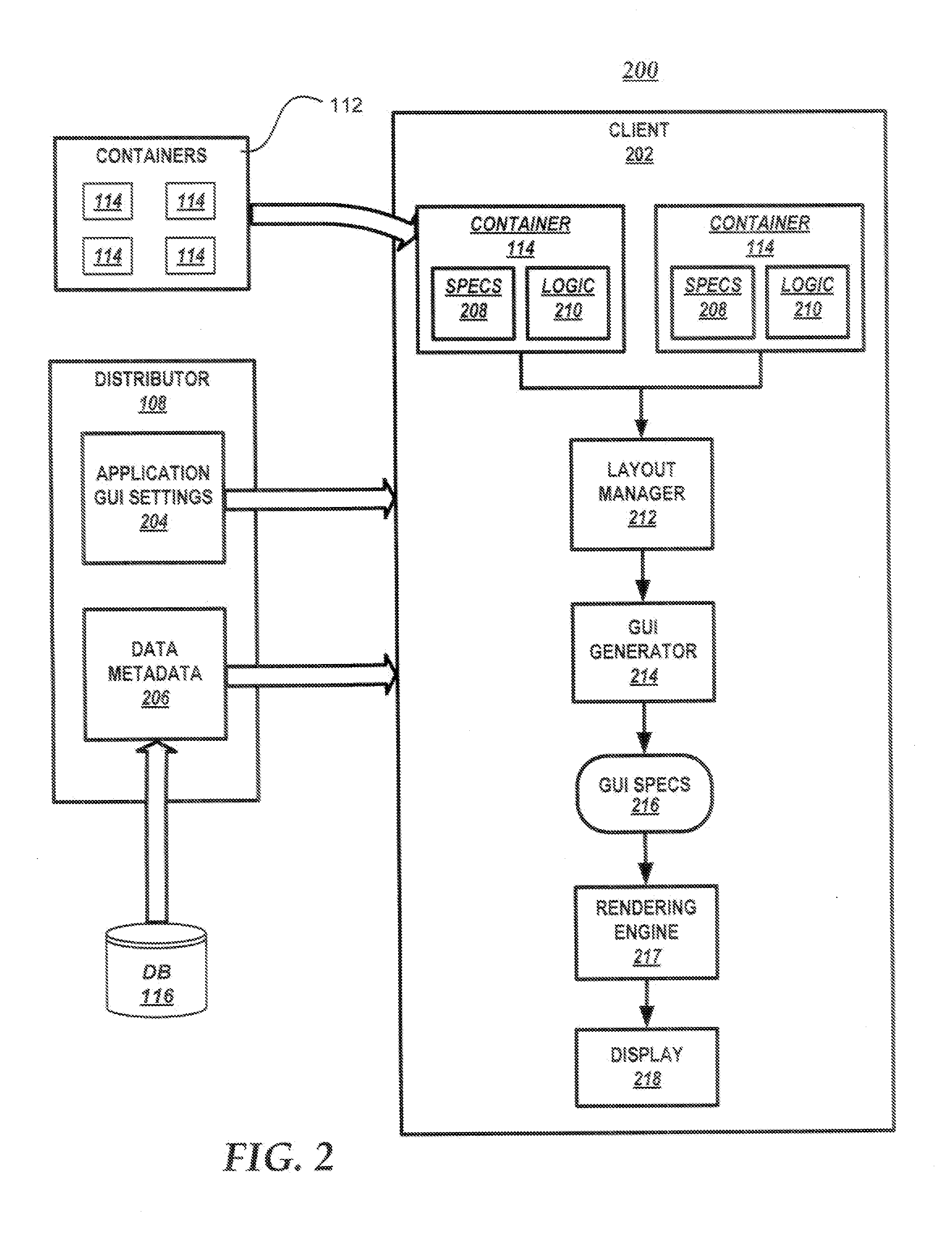
A system and method for laying out graphical user interface elements at a client device. A client device receives a set of containers, each container including program instructions and specifications. The program instructions of each container are executed to determine a size and position of each graphical user interface element. Each type of container has corresponding logic upon which sizing and positioning of graphical user interface elements is based. The client device may receive data metadata descriptive of the graphical user interface elements and application specifications. Sizing and positioning of the graphical user interface elements may be based on the data metadata and application specifications. A layout process may recursively descend a structure of containers to determine sizes and positions of each GUI element.

Description

BACKGROUNDThe design and specification of a graphical user interface by a developer can be a complex task. Often, requirements of the graphical user interface (GUI) may change during the development process, or after it is complete. This may cause a developer to perform large portions of the design and specification process multiple times. Typically, an application is intended to execute in a variety of environments, including differing display properties. Developers may need to become familiar with the different environments to create a GUI that has a consistent appearance. Development of a GUI is subject to errors of not accounting for one or more environments. An example of this is a GUI that may be correct when a window is a normal size, but one or more of the GUI elements does not adjust properly when the window is maximized.SUMMARYThis Summary is provided to introduce a selection of concepts in a simplified form that are further described below in the Detailed Description. Thi...

Claims


Application Information

Patent Timeline
IPC IPC(8): G06F3/048
CPCG06T11/206
Inventor YAN, XINBINDER, JOSEPH S.
Owner MICROSOFT TECH LICENSING LLC
Learn More