Compact support clamp with rotating equipment attachment and jaw operator

Active Publication Date: 2011-05-05
PRYOR PRODS
View PDF6 Cites 42 Cited by
  • Summary
  • Abstract
  • Description
  • Claims
  • Application Information

AI Technical Summary

Benefits of technology

[0013]In a further embodiment of the invention, two rotational elements are incorporated so that the position of the attached equipment can be varied to limit interference between multiple clamps attached to the same support. The second index plate is mounted

Problems solved by technology

This creates an elongated profile that may interfere with other clamps or structures carried on the support.
In the past rotational capability has required substantial further protrusions from the clamp body to accommodate the

Method used


Image

  • Compact support clamp with rotating equipment attachment and jaw operator
  • Compact support clamp with rotating equipment attachment and jaw operator
  • Compact support clamp with rotating equipment attachment and jaw operator

Examples


Example

DETAILED DESCRIPTION OF THE DRAWINGS

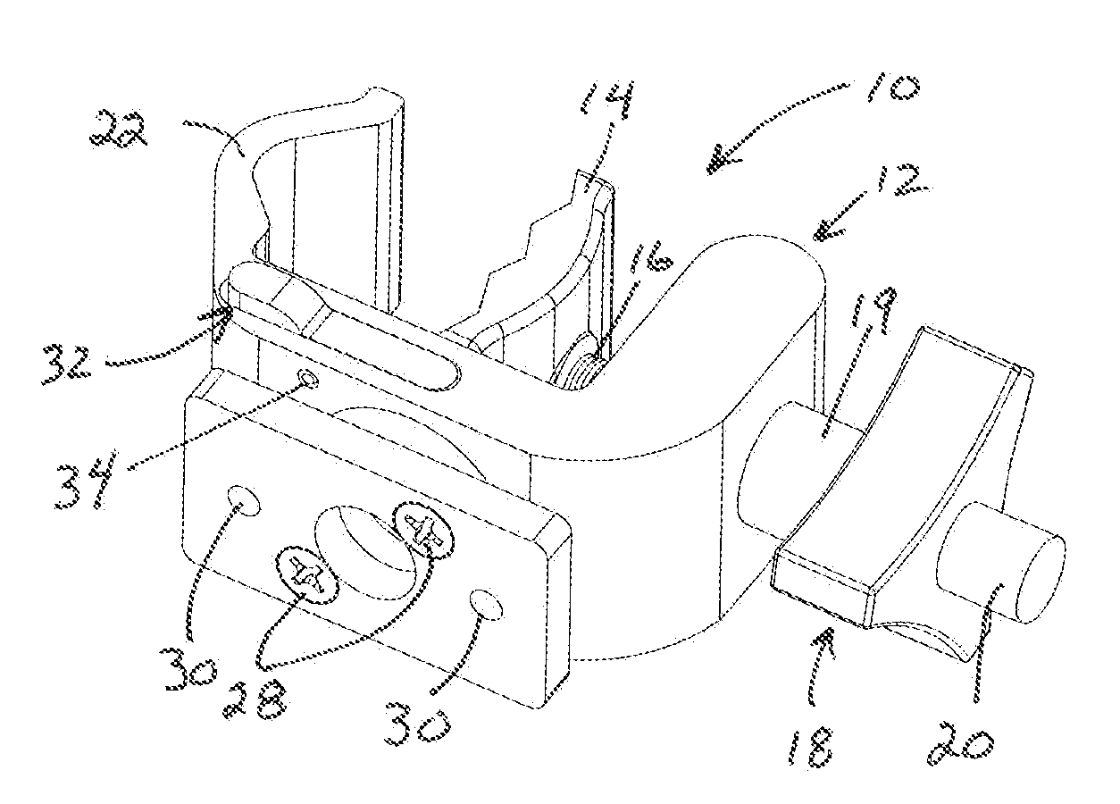
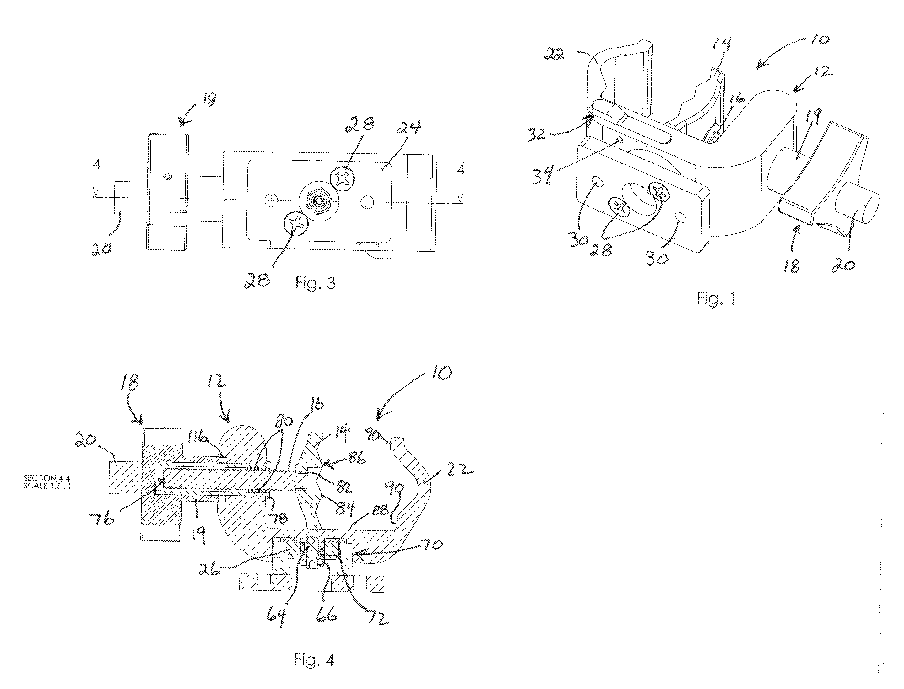
[0031]FIG. 1 shows the single rotational axis clamp (10) with a clamp body (12). The thruster plate (14) is attached to a screw (16) that is advanced / retracted by operation of the enlarged knob (18) which rotates the thruster cylinder (See FIG. 4). The thruster cylinder is in threaded engagement with the screw (16). The enlarged knob (18) has a knurled extension (20) for rapid rotation to bring the thruster plate (14) into engagement with a support (not shown) and to retract the thruster plate (14) after the tension on the support is released by use of the enlarged knob (18). The enlarged knob has a cylindrical extension (19) which surrounds the thruster cylinder and thereby provides room for the screw (16) to retract. The clamp (10) has a fixed jaw (22) opposed to the thruster plate (14). A mount plate (24) is secured to a index wheel (26) (See FIG. 4) by fasteners (28). The mount plate incorporates two mounting bores (30) through which fasteners...


PUM


Abstract

The device utilizes a thruster cylinder driven by a enlarged knob and terminating in a thruster plate to clamp to a support. Provision is made to attach a device to the clamp through a rotating index wheel which can lock the device by receiving a tang from a trigger lever at a selected increment of rotation. A second embodiment has two index wheels so that the attached device can be displaced in one of four directions to avoid conflict with other devices on the same support. The second axis is normally used to return a displaced device to an upright orientation.

Description

BACKGROUND OF THE INVENTION[0001]In various applications structures such as equipment must be mounted from a support in proximity to the location where the equipment is utilized. This requirement is especially common with medical equipment that must be supported near where the equipment is utilized for medical treatment of patients.[0002]Clamps with features for mounting equipment are known that are secured to existing supports such as tubular supports as in IV poles (vertical) and bed rails (horizontal). Clamps have also been utilized with planar supports such as table edges.[0003]A typical clamp may comprise a c-clamp shape that grasps a support between a fixed jaw and a moveable jaw. The jaw operator mechanism for moving the moveable jaw into engagement with and securely grasping the support has typically utilized a screw carried in a threaded opening in the clamp body. This screw, of necessity, must be of a length greater than the maximum distance between the fixed and moveable ...

Claims


Application Information

Patent Timeline
IPC IPC(8): B25B5/02B25B5/10B25B5/16
CPCB25B5/101B25B5/006A61B90/57A61B90/50A61G7/0503A61M5/1414A61M5/1418F16B2/12F16M13/022A61B2090/571A61B90/60
Inventor QUINTANIA, RICHARD ENOCHCOX, JAMES MARK
Owner PRYOR PRODS
Why Eureka
Try Eureka